Device for holding and rotating plate shaped article

a technology of rotating parts and rotating parts, which is applied in the direction of semiconductor/solid-state device manufacturing, basic electric elements, electric apparatus, etc., can solve the problems of chuck pins being prone to be affected, complex structure and control, and difficult process, etc., and achieves convenient control of the rotation angle of the pivot pin, simple structure, and small space occupation

Active Publication Date: 2019-02-12
BEIJING SEVENSTAR ELECTRONICS CO LTD
View PDF5 Cites 3 Cited by
  • Summary
  • Abstract
  • Description
  • Claims
  • Application Information

AI Technical Summary

Benefits of technology

[0009]Accordingly, an objective of the present invention is to provide a novel rotatory holding device for a plate shaped article with simple structure, easy and reliable motion control, and controllable clamping force, to overcome the above defects of the existing technology including structural complexity, processing difficulties, susception to the centrifugal force and the gravity, and particle generation.
[0023]As is disclosed above, according to the present invention, by providing a group of fixed pins and a group of pivot pins arranged circumferentially along the movable base in a manner that each pivot pin opposites a fixed pin, and by positioning magnetic bodies within the pivot pins and outside two opposing sides of the pivot pins and driving each pivot pin to rotate around its pivot back and forth under the magnetic repulsive force between two adjacent magnetic bodies to release or clamp the plate shaped article, the adverse impact of the centrifugal force and the gravity on the clamping actions of the pivot pins can be avoided, reliable clamping to the plate shaped article can be achieved. Furthermore, with the ascending and descending of the lifting mechanism and the spacing of the chamber accommodating the pivot pin, the rotation of the pivot pin can be achieved and the rotation angle of the pivot pin can be controlled conveniently; with the appropriate selection of the magnetic bodies, a proper clamping force acting on the edge of the plate shaped article by the pivot pin can be realized. In addition, it also achieves convenience for maintenance and small space occupation for the processing chamber. Accordingly, the present invention has advantages of simple structure, convenient and reliable action control, controllable clamping force and good compatibility with various processing chambers.

Problems solved by technology

However, the above conventional devices for holding and rotating a plate shaped article all exist many problems like complexity in structure and control, and process difficulties.
Particularly, the conventional chuck pins are prone to be affected by the centrifugal force and the gravity during the high speed rotation of the rotatable chuck, which requires extra design considerations in addition to the safety standard design or a relative short return stroke; on the other hand, mutual actions among more chuck pins may easily cause pollution due to the particles generated by friction.
For the device applying electrostatic adhesion or gas cushion to hold the plate shaped article, it requires complicated design of control system and appropriate timing to control and move the chuck pins, or even specialized and expensive axis linkage rotary mechanisms.
Furthermore, the conventional rotatable holding devices for plate like articles do not provide advantageous design in terms of control of the clamping force of the chuck pins, always resulting in product damages and particle generation during clamping the plate shaped article.

Method used


Image

  • Device for holding and rotating plate shaped article
  • Device for holding and rotating plate shaped article
  • Device for holding and rotating plate shaped article

Examples


Embodiment Construction

[0030]The invention will be described in further details hereinafter with reference to specific embodiments and accompanying drawings.

[0031]Note that in the following embodiment, all the accompanying drawings referred to are not necessarily drawn to scale, should be understood to be enlarged or distorted or simplified relative to others to facilitate convenience and clearness in explanation and understanding of the present invention, and not limit the scope of the invention.

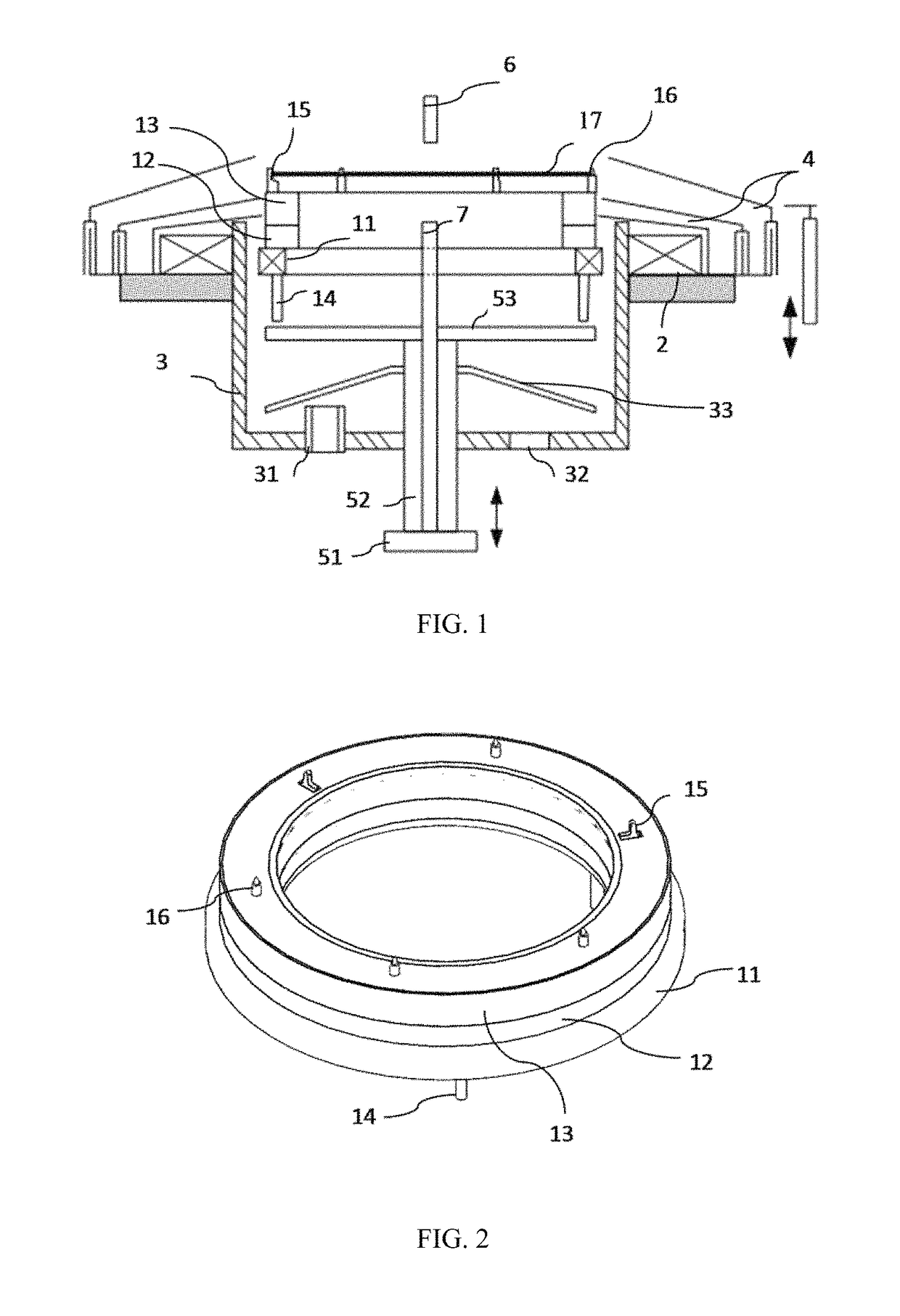
[0032]Please refer to FIG. 1, FIG. 1 is a structure diagram showing a device for holding and rotating a plate shaped article according to an embodiment of the present invention. As shown in FIG. 1, the device for holding and rotating a plate shaped article comprises an annular movable base 13, an annular fixed base 12 and a rotatable chuck 11 which are arranged concentrically from up to down. The movable base 13 is provided with a group of fixed pins 16 and a group of pivot pins 15 which are arranged circumferent...


PUM


Abstract

A device for holding and rotating a plate shaped article comprises a group of fixed pins and a group of pivot pins arranged along the circumference of the movable base in a manner that each pivot pin opposites a fixed pin, and also comprises magnetic bodies positioned within and outside two opposing sides of the pivot pins. Each of the pivot pins can be driven to rotate around its pivot back and forth under the magnetic repulsive force between two adjacent magnetic bodies, so as to release or clamp the plate shaped article. The present invention has advantages of simple structure, convenient and reliable action control, controllable clamping force and good compatibility with various processing chambers.

Description

CROSS-REFERENCE TO RELATED APPLICATION[0001]This application claims the priority benefit of International Patent Application Serial No. PCT / CN2015 / 083727, filed Jul. 10, 2015, which is related to and claims the priority benefit of China patent application serial No. 201410851693.5, filed Dec. 31, 2014. The entirety of each of the above-mentioned patent applications is hereby incorporated by reference herein and made a part of this specification.FIELD OF THE INVENTION[0002]The present invention generally relates to the field of semiconductor manufacturing equipment, and more particularly, to a device for holding and rotating a plate shaped article.BACKGROUND OF THE INVENTION[0003]During the manufacturing process for integrated circuits, circular plate shaped articles like semiconductor chips of silicon or wafers are subjected to various processes such as film deposition, etching, cleaning, polishing, etc. During such processes, the plate shaped article is supported, clamped and rotat...

Claims


Application Information

Patent Timeline
Patent Type & Authority Patents(United States)
IPC IPC(8): H01L21/687H01L21/67
CPCH01L21/68721H01L21/6875H01L21/68764H01L21/68728H01L21/67051
Inventor ZHANG, BAOJI, DANDANWANG, RUITINGWU, YI
Owner BEIJING SEVENSTAR ELECTRONICS CO LTD
Why Eureka
Try Eureka