Dynamic effective radiated power (ERP) adjustment

a technology of effective radiated power and adjustment field, applied in the field of dynamic effective radiated power adjustment, can solve the problems of complex antenna pattern, esd limits, and used antennas, and achieve the effect of reducing the instantaneous power output of amplifiers

Active Publication Date: 2019-02-19
GOGO BUSINESS AVIATION LLC
View PDF8 Cites 4 Cited by
  • Summary
  • Abstract
  • Description
  • Claims
  • Application Information

AI Technical Summary

Benefits of technology

[0011]The amplifier instantaneous power output may be used to provide antenna input power, which may be measured to calculate the transmitted EIRP and used to verify that the transmitted EIRP is less than a maximum allowable transmitted EIRP based upon the ESD limit for the target scan angle and the target skew angle. In the event that the transmitted EIRP exceeds the maximum allowable transmitted EIRP, the amplifier instantaneous power output may be reduced accordingly.
[0012]Throughout the disclosure, the term “EIRP,” or effective isotropic radiated power, is used as regulatory agencies typically use this terminology. However, it will be understood that the embodiments discussed herein may be modified to be applicable to any measurement of effective radiated power (ERP) in an antenna system. For example, the techniques described herein are equally applicable to systems that utilize an ideal dipole reference for an ERP calculation as opposed to an ideal isotropic radiator.

Problems solved by technology

Due to the unique requirements associated with the airborne environment, the antennas used on board aircraft for communications may have complex antenna patterns that may vary as the aircraft moves throughout a given coverage area.
As a consequence, the variations of antenna gain result in ESD limits that vary as a function of scan angle, skew angle, and frequency.
However, since aTDMA transmissions can vary in frequency, power, and bandwidth on very short timescales, they introduce significant complexities in the monitoring of the ESAA's instantaneous ESD.
However, this method has proven to be inflexible because it limits transmission to below the ESD limit for other scan / skew combinations when, for example, an ESAA antenna exhibiting a variable gain is capable of transmitting at the ESD limit across other scan / skew angles but is otherwise limited by the power output calculated in accordance with the minimum ESD.

Method used


Image

  • Dynamic effective radiated power (ERP) adjustment
  • Dynamic effective radiated power (ERP) adjustment
  • Dynamic effective radiated power (ERP) adjustment

Examples


Embodiment Construction

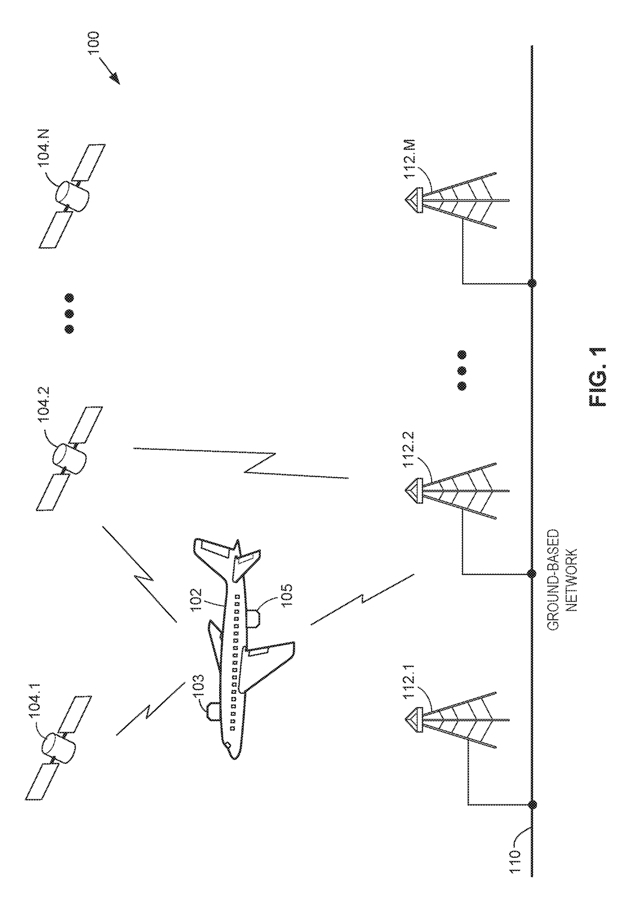
[0020]FIG. 1 illustrates an example communication system 100 in accordance with an embodiment of the present disclosure. In the present embodiments, communication system 100 may include a vehicle 102, any suitable number N of satellite communication systems 104.1-104.N, any suitable number M of ground-based stations 112.1-112.M, and a ground-based network 110. Communication system 100 may include additional, less, or alternate components, including those discussed elsewhere herein. Furthermore, for the sake of brevity, communication system 100 is illustrated as including a single vehicle 102. However, the aspects described herein may include any suitable number of such vehicles.

[0021]Vehicle 102 may include one or more stations 103 and / or 105, as shown in FIG. 1. Stations 103 and / or 105 may be mounted to, located within, or otherwise associated with vehicle 102 to facilitate communications between vehicle 102, one or more satellite communication systems 104.1-104.N, and / or one or mo...


PUM


Abstract

Antennas used aboard aircraft to communicate with satellites or ground stations may have complex antenna patterns, which may vary as the aircraft moves throughout a given coverage area. Techniques are disclosed for dynamically adjusting the instantaneous power fed to an antenna system to ensure that the antenna transmits at the regulatory or coordinated effective isotropic radiated power (EIRP) spectral limit. The antenna may transmit, in accordance with aircraft location and attitude, steerable beam patterns at different scan and skew angle combinations, causing variations in antenna gain and fluctuations in the transmitted EIRP. Using on-board navigational data, an antenna gain and ESD limit may be calculated for a particular scan and skew angle, which may be used to adjust power fed to the antenna such that the antenna transmits substantially at maximum allowable EIRP as the steerable beam pattern is adjusted.

Description

CROSS-REFERENCE TO RELATED APPLICATIONS[0001]This application claims priority to Provisional Application No. 62 / 357,570, entitled “Dynamic Effective Radiated Power (ERP) Adjustment,” and filed on Jul. 1, 2016, which is incorporated herein by reference in its entirety.TECHNICAL FIELD[0002]The present disclosure describes a means to continuously adjust the dynamic range of a station based on location, attitude (roll, pitch, yaw), and antenna characteristics, such that the instantaneous maximum output power available to the station corresponds to the regulatory or coordinated effective isotropic radiated power (EIRP) spectral density limit.BACKGROUND[0003]For certain types of stations such as earth stations aboard aircraft (ESAA), for example, transmission towards a satellite (or ground-based stations) is limited by off-axis effective isotropic radiated power (EIRP) spectral density (ESD). That is, to prevent interference with adjacent satellites or ground-based stations, earth station...

Claims


Application Information

Patent Timeline
Patent Type & Authority Patents(United States)
IPC IPC(8): H01Q3/28H01Q3/26G01C21/20H04B7/185H04W16/28G01S19/02H01Q1/28
CPCH01Q3/28G01C21/20G01S19/02H04B7/18506H04W16/28H01Q3/267H04B7/18508H01Q1/28Y02D30/70
Inventor DANG, TUAN M.CORDONE, SEAN SCOTTBRUGGEMANN, JEFF
Owner GOGO BUSINESS AVIATION LLC
Why Eureka
Try Eureka