Eureka AIR delivers breakthrough ideas for toughest innovation challenges, trusted by R&D personnel around the world.

Composite isolation joint for gap sub or internal gap

a technology of electromagnetic and sub-internal gap, which is applied in the field of isolation technology in electromagnetic (“ em”) telemetry, can solve the problems of reducing the effectiveness of the em system in communicating via the earth's strata, weak em waves transmitted by the transceiver on the drill string, and the loss of the character of the lower drill string, so as to achieve robust electrical isolation, improve performance and durability, and improve durability

Active Publication Date: 2019-03-05
PRIME DOWNHOLE MANUFACTRUING LLC
View PDF37 Cites 4 Cited by
  • Summary
  • Abstract
  • Description
  • Claims
  • Application Information

AI Technical Summary

Benefits of technology

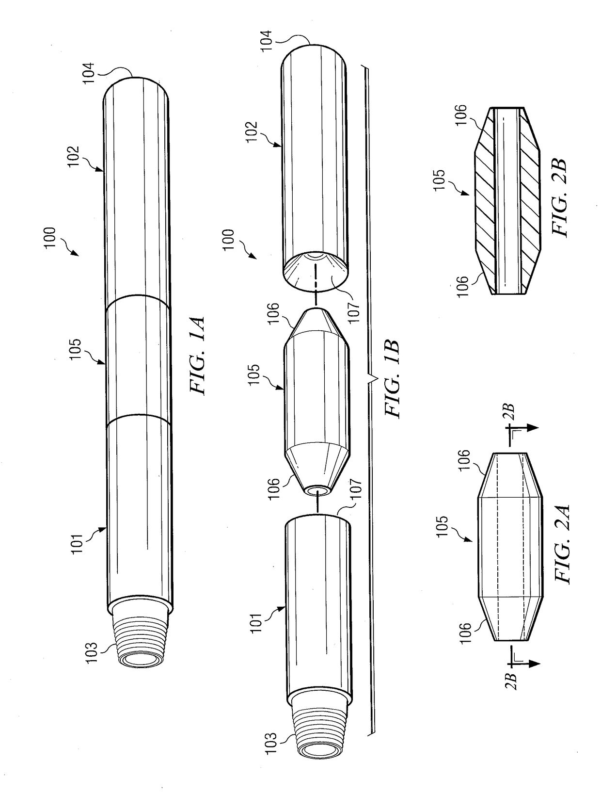
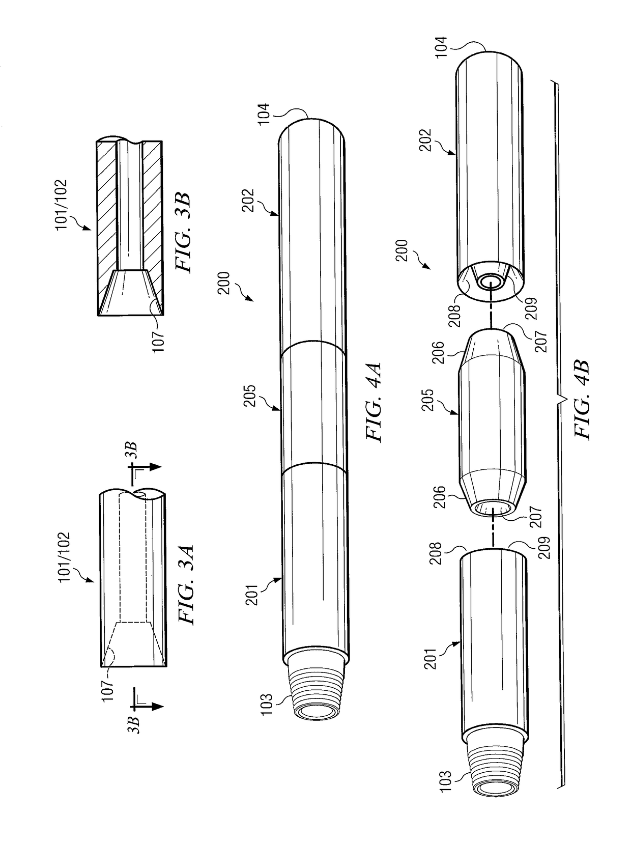
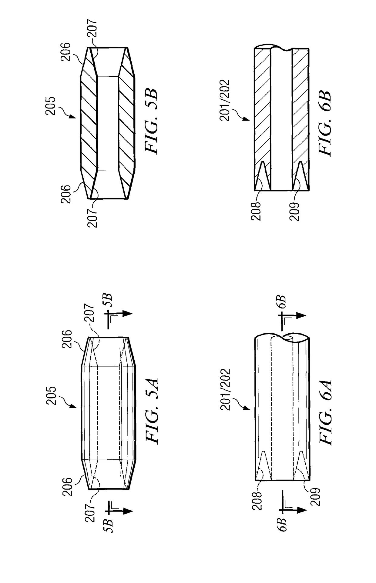
[0015]The composite insert provides a tapered transition into the conductive portions of the gap sub (typically made of metal) at either or both ends of the insert. The transitions on the composite insert may comprise one or more tapered surfaces, which may be male or female in configuration with respect to a matching transition on the conductive portions of the gap sub. The composite insert is bonded to its matching conductive portions, preferably by gluing or threading. An optional protective sleeve may be deployed on the outer surface of the gap sub at the composite-to-metal interfaces to protect the transition and maintain a constant outer diameter on the collar or internal tooling. The protective sleeve may be made from materials such as plastic or metal, so long as the electrical isolation is preserved, and may be attached by any method typical in the field, such as gluing or threading.
[0019]It is therefore a technical advantage of the disclosed gap sub to provide excellent (almost complete) drill collar isolation either side of the above-described electrically isolating composite joints. As noted, deployment of the composite isolating joint enables a robust electrical isolation either side of the joint. As a result, optimized EM wave propagation is provided back and forth through the Earth's strata between the lower drill string (i.e. below the gap sub) and the surface.
[0020]A further technical advantage of the disclosed gap sub is to provide sustained electrical isolation either side of the above-disclosed composite joints in a wide range of operating conditions. Modern directional drilling operations require the drill string to undergo bending loads and cyclic vibration loads as the borehole changes direction. Historically, these loads have been known to crack or fracture electrically isolating members deployed on previous gap subs, causing loss of isolation. However, the non-conductive composite inserts, as configured on the new electrical isolation joint disclosed herein, have been shown to be very robust, even when the gap sub is undergoing high operational stresses, such as high bending loads or vibrations. For example, one embodiment of the inventive content of this disclosure has been field tested via deployment in an air drilling job. The high-vibration environment of air drilling typically results in severe damage to electrical isolation joints employing ceramic coated threads. Premature failure of such ceramic coated joints has been observed when deployed in a high-vibration environment. By contrast, the disclosed composite isolation joint performed as designed and expected throughout the air drilling field test, providing improved performance and durability, even in harsh operating environments.
[0021]The disclosed inventive content also provides additional technical advantages. Because of its improved durability, the composite joint can become a consumable part rather than a serviced part. As a consumable item, users are not required to schedule service visits with vendors that are not readily available world wide. Further, improved durability and performance may reduce overall drill string downtime.

Problems solved by technology

Any loss in complete electrical isolation will cause the lower drill string to start to lose its character as an antenna, reducing the effectiveness of the EM system in communicating via the Earth's strata.
A further “reality” is that the EM waves transmitted by the transceiver on the drill string are likely to be weak in comparison to their counterparts transmitted from the surface because local power available to a transceiver on a tool string is limited.
Thus, any wave propagation loss via poor isolation between upper and lower portions of the drill string is likely to cause a magnified reduction in effectiveness of the tool string transceiver's transmissions, as compared to surface transmissions.
When internal and external gaps are separated, the quality of the “jump” of EM transmissions across the gap and into the surrounding formation may be compromised.
These failures can cause unacceptable loss of isolation, and corresponding loss in EM telemetry, during live drilling operations.

Method used


Image

  • Composite isolation joint for gap sub or internal gap
  • Composite isolation joint for gap sub or internal gap
  • Composite isolation joint for gap sub or internal gap

Examples


Embodiment Construction

[0034]FIGS. 1A and 1B illustrate, in assembled and disassembled form respectively, perspective views of one embodiment of a composite isolation joint gap sub 100. In FIG. 1A, gap sub 100 comprises pin end portion 101 and box end portion 102 separated by composite portion 105. The pin end portion 101 and box end portion 102 are made from a conductive material, which may advantageously further be a non-magnetic material such as stainless steel (although the inventive material disclosed herein is not limited in this regard). The composite portion 105 is made from a non-conductive composite material, such as a glass-fiber reinforced plastic. Composite portion 105 may also be made from, for example, a proprietary composite available from Advanced Composite Products & Technology, Inc. of Huntingdon Beach, Calif., identifiable as “DWG 3995 REV A”. It will be nonetheless appreciated that the inventive material in this disclosure is not limited in any way to use of this specific composite.

[0...


PUM


Abstract

A non-conductive composite insert is provided between conductive portions, useful, for example, in downhole EM telemetry applications as an external "gap sub" in a drill collar, or as a sonde-based internal gap. In a preferred embodiment, the composite is made from a glass-fiber reinforced plastic, and separates non-magnetic conductive portions made from stainless steel. The composite insert provides a slanted or tapered transition into the conductive portions at either or both ends of the insert. The transitions on the composite insert may comprise one or more tapered surfaces, which may be male or female in configuration with respect to matching transitions on the conductive portions. The transitions may be bonded together by adhesive, or alternatively may be threaded.

Description

RELATED APPLICATIONS[0001]This application claims the benefit of, and priority to, commonly-invented and commonly-assigned U.S. Provisional Application Ser. No. 61 / 781,821 filed Mar. 14, 2013.FIELD OF THE INVENTION[0002]This disclosure is directed generally to technology useful in measurement-while-drilling (“MWD”) applications in the oil and gas exploration field, and more specifically to isolation technology in electromagnetic (“EM”) telemetry.BACKGROUND OF THE INVENTION[0003]Ultra-low frequency (ULF) electromagnetic (EM) waves are the preferred transmission mechanism for wireless subterranean telemetry applications due to the ULF wave's ability to propagate long distances through the Earth's strata. In a typical subterranean telemetry application, the desired telemetry information is digitally encoded into data packets and sent as modulated “bursts” of ULF carrier waves. Transmission of the carrier waves is physically facilitated by injecting a modulated current into the Earth me...

Claims


Application Information

Patent Timeline
Patent Type & Authority Patents(United States)
IPC IPC(8): E21B17/00E21B47/12
CPCE21B47/122E21B17/003E21B47/13
Inventor MACDONALD, CRAIGMILLER, MARK
Owner PRIME DOWNHOLE MANUFACTRUING LLC
Why Eureka
Eureka Blog
Learn More