Ignition system and method for operating an ignition system for an internal combustion engine

a technology of ignition system and internal combustion engine, which is applied in the direction of automatic control of ignition, machines/engines, mechanical equipment, etc., can solve the problems of secondary voltage generator increasing erosion, and reducing the service life of the ignition system

Active Publication Date: 2019-03-05
ROBERT BOSCH GMBH
View PDF13 Cites 0 Cited by
  • Summary
  • Abstract
  • Description
  • Claims
  • Application Information

AI Technical Summary

Benefits of technology

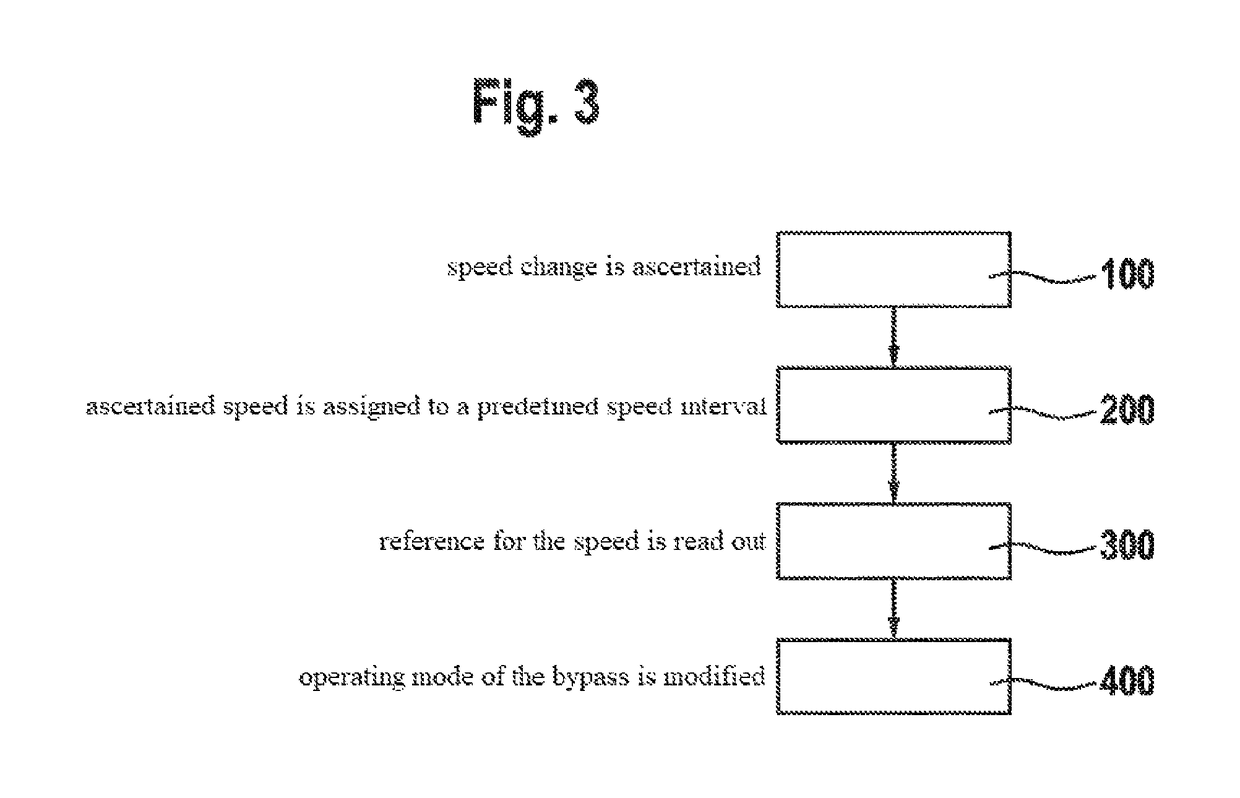
[0004]The aforementioned object may be achieved according to the present invention by a method for operating an ignition system for an internal combustion engine, including one first voltage generator (“primary voltage generator”) and one bypass for maintaining a spark generated with the aid of the primary voltage generator. The bypass in this case may include, in particular, a boost converter or may be configured as a boost converter. A spark generated by the primary voltage generator (for example, a step-up transformer) is supported by the bypass in a suitable manner by energy drawn from the vehicle electrical system. According to the present invention, a speed of an internal combustion engine used with the ignition system is ascertained. This may take place, for example, as a readout of a digital control signal (for example, via a signal line or a bus system) or a calculation of the speed based on the change of the crank angle of the internal combustion engine over time. In this way, a speed change of the internal combustion engine may be ascertained. The operating mode of the bypass is modified in response to the altered speed. In this way, the energy, with the aid of which the bypass supplies the ignition spark, may be controlled as a function of an instantaneous operating state of the internal combustion engine. Since, according to the present invention, a dose of ignition spark energy provided via the bypass occurs as a function of the respective operating state, it is possible to reduce spark erosion on the electrodes of the ignition system. The generation of heat loss in the boost converter is also reduced. Another advantage to be cited is the robustness and the durability of the ignition system.
[0016]The ignition system may be configured to evaluate a crank angle over time via an electrical control or an analog circuit, a microcontroller, an ASIC or an FPGA within the ignition system, in order to ascertain a speed change. This makes it possible to use hardware already existing in conventional ignition systems. The aforementioned hardware may be situated, for example, in an electronics unit of the ignition system. This makes a simple construction and implementation of the present invention possible without additional hardware.

Problems solved by technology

Due to the discharge characteristics of the high voltage generator, a current flows, in particular, at the start of the spark discharge, that is so high that the electrodes of the spark gap become eroded.
In the process, a spark duration prolonged with the aid of the secondary voltage generator increases erosion.

Method used


Image

  • Ignition system and method for operating an ignition system for an internal combustion engine
  • Ignition system and method for operating an ignition system for an internal combustion engine
  • Ignition system and method for operating an ignition system for an internal combustion engine

Examples


Embodiment Construction

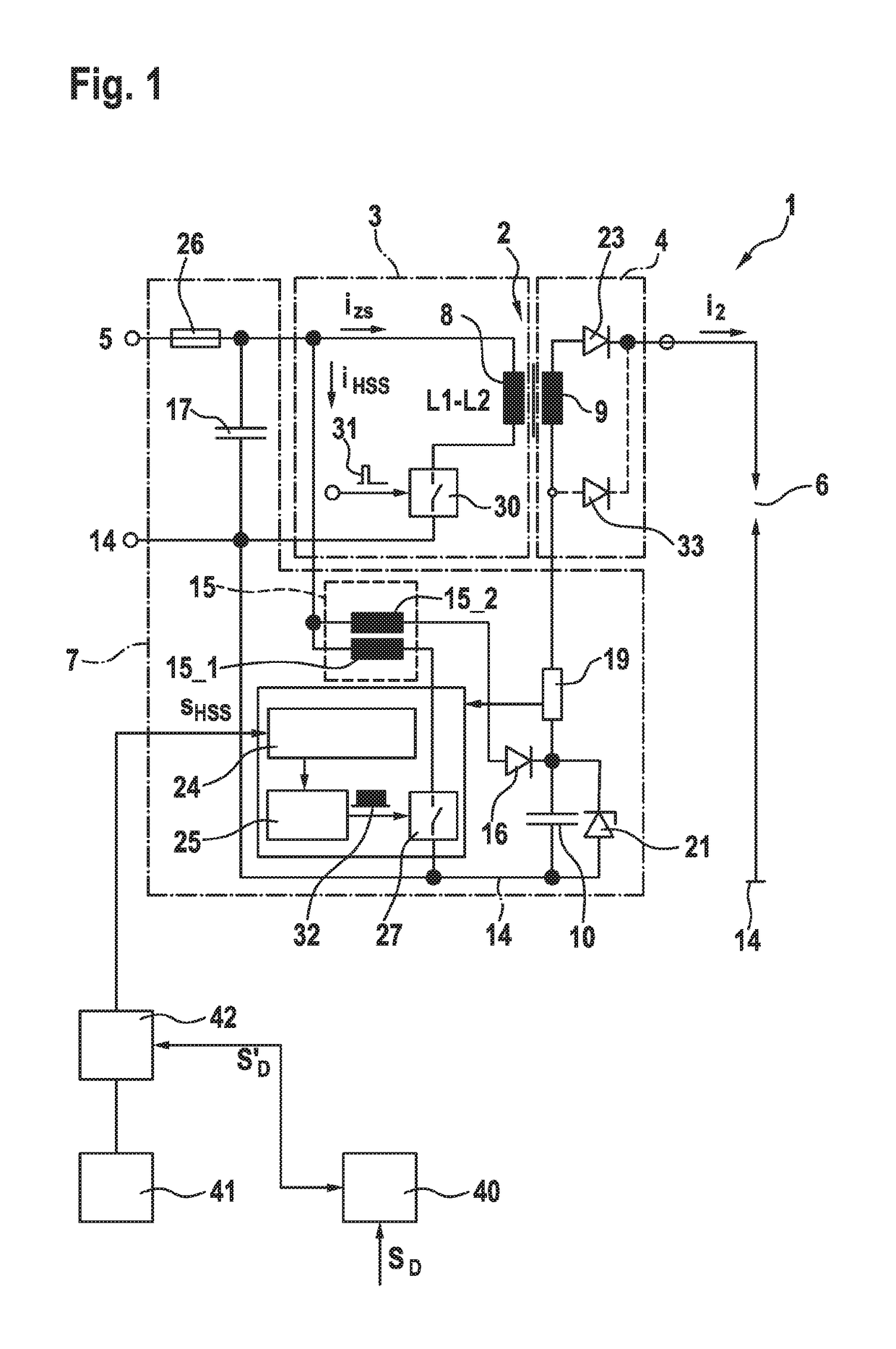
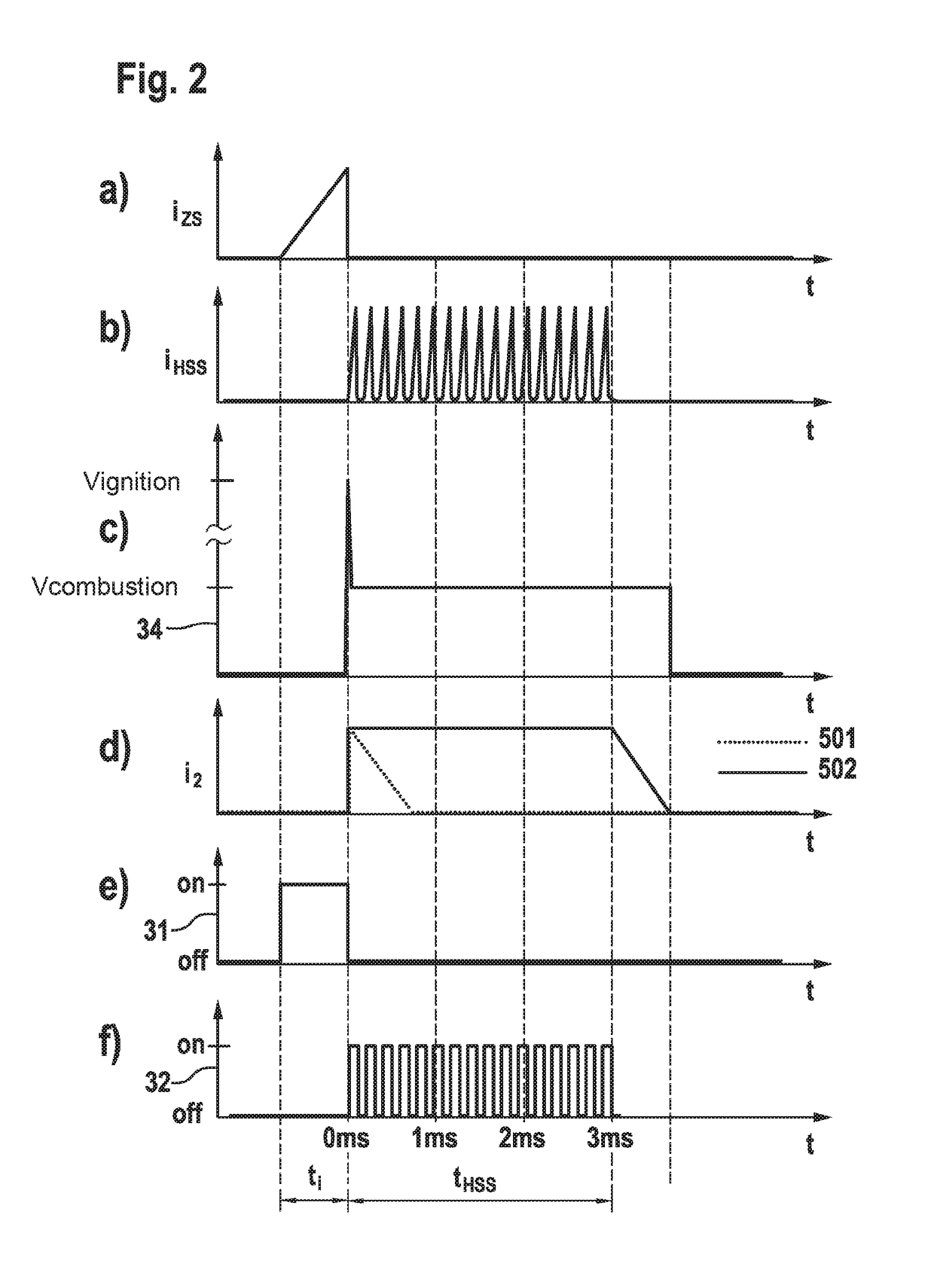
[0022]FIG. 1 shows a circuit of an ignition system 1, which includes a step-up transformer 2 as a high voltage generator, which is made up of two coupled inductances L1, L2, namely, a primary coil 8 and a secondary coil 9, and the primary side 3 of which may be supplied with energy from an electrical energy source 5 via a first switch 30. A fuse 26 is provided at the input of the circuit, in other words, therefore, at the terminal with electrical energy source 5. In addition, a capacitance 17 for stabilizing the input voltage is provided in parallel to the input of the circuit or in parallel to electrical energy source 5. Secondary side 4 of step-up transformer 2 is supplied with electrical energy via an inductive coupling of primary coil 8 and secondary coil 9, and includes a diode 23 known from the related art for suppressing the powering spark, this diode being alternatively substitutable with a diode 21. A spark gap 6, via which ignition current i2 is intended to ignite the comb...


PUM


Abstract

A method for operating an ignition system for an internal combustion engine, including a first voltage generator and a bypass, is described. The bypass may include, for example, a boost converter for maintaining a spark generated with the aid of the first voltage generator. A speed of an internal combustion engine used with the ignition system is ascertained and the operating mode of the bypass is modified in response to the speed change.

Description

FIELD OF THE INVENTION[0001]The present invention relates to a method for operating an ignition system for an internal combustion engine. The present invention relates, in particular, to improvements in wear prevention in such ignition systems, in which the spark duration is controllable.BACKGROUND INFORMATION[0002]Ignition systems for internal combustion engines are known to be based on a high voltage generator, with the aid of which energy originating from the vehicle battery is converted into high voltages, which are applied at a spark gap in order to ignite a combustible mixture in the internal combustion engine. In this process, a current flowing through the step-up transformer is abruptly interrupted, whereupon the energy stored in the magnetic field of the step-up transformer discharges in the form of a spark. Once the stored energy is discharged, the ignition spark is extinguished. Ignition systems are also known in the related art, in which the first voltage generator (“pri...

Claims


Application Information

Patent Timeline
Patent Type & Authority Patents(United States)
IPC IPC(8): F02P3/04F02P15/10F02P5/15F02P9/00F02P17/12
CPCF02P9/007F02P3/0407F02P3/0442F02P5/1502F02P15/10F02P5/1514Y02T10/46F02P5/1516F02P2017/121Y02T10/40
Inventor SKOWRONEK, TIMPAWLAK, THOMASSINZ, WOLFGANG
Owner ROBERT BOSCH GMBH
Why Eureka
Try Eureka