Standard light source color matching observation box

a color matching and light source technology, applied in the field of detection structure, can solve the problems of difficult to ensure, difficult to achieve, and difficult to achieve the effect of ensuring the relative spectral power distribution of light emitted from the light source, and achieving the effect of gentle spectral power distribution curve and improving the stability of the light sour

Active Publication Date: 2019-03-05
WENZHOU JIAYI INSTR
View PDF0 Cites 0 Cited by
  • Summary
  • Abstract
  • Description
  • Claims
  • Application Information

AI Technical Summary

Benefits of technology

[0007]It is an object of the present invention to overcome the shortcomings of the prior art and to provide a standard light source color matching observation box which is simple in structure, achieves a stable simulation of D illuminants, and ensures test accuracy.
[0018]The present invention has the advantages that the light ray transmitted through the halogen tungsten lamp emits the radiation light ray before being compensated through the light filter; the narrow-wave LED light source is provided to emit the compensated light; the radiation light ray before being compensated and the compensation light are mixed in the color matching observation box to become the radiation light ray after being compensated; the radiation light ray after being compensated performs color measurement to the measured objects in the color matching observation box. The light ray emitted by the halogen tungsten lamp is used as the main body radiation light ray, which may have a more gentle spectral power distribution curve. The lack of energy of the halogen tungsten lamp through the light filter is compensated for by the low-power narrow-wave LED light source, which can be simulated into high-precision D illuminator of the CIE standard. The combination of a halogen tungsten lamp configured filter and a narrow-wave LED light source can simulate D illuminators of different specifications, D65, D75, D55, D50. It can be achieved by adjusting the brightness of the narrow-wave LED light source. The quality of the compensated light source is <0.2 A level according to the metamerism index specified by D illuminant of the CIE standard, which is difficult to achieve with the original light source; and it improves the stability of the light source, so that in the process of using the light source, it will not have changes in radiation light ray color temperature. The compensation light ray is adjusted by the automatic monitoring so that the radiation light ray color temperature is compliant with the standard, to ensure the accuracy of the result of a long-time color measurement.

Problems solved by technology

However, due to the influence of the material and the manufacturing process technology, it is difficult for the technical indicator of the relative spectral power distribution of its function for irradiating the light source to achieve the A-level metamerism index quality level <0.2 of the CIE D-standard illuminant.
As the halogen tungsten lamps of the same specification have a difference in material composition, and the relative spectral power distribution of the light emitted therefrom cannot have a relatively consistent quality.
The prior art makes it difficult to ensure that the standard light source continues to have a stable spectral power distribution after prolonged use, and the replacement of the halogen tungsten lamp or the light filter will produce a difference, thus affecting the accuracy of the test.
Since the spectral distribution of the light ray emitted by the LED can only be in the narrow wavelength band, and the main peak of the spectrum emitted by each LED is narrowed into spikes, although the light rays of three narrow waves of red, green and blue can form an integrity to emit white light, its spectral power distribution has defects.
So a multi-stage narrow-band LED is used to combine to emit light to illuminate the spectral power distribution close to the specification requirements of the D illuminant specified by the CIE standard, but the relative spectral power distribution of the light ray that it illuminates the position in which objects are stored in the standard light source color matching observation box is non-uniform.
Although the current general color temperature measuring instrument is used to measure its color temperature value so as to achieve the D light source indicators specified by the CIE standard, it is very difficult for the metamerism index of the light source emitted therefrom to reach A level.
It is still very difficult for the radiation uniformity to have a good uniformity on the surface of the sample to be measured.
The naked-eye visual observation is completed by those skilled in the art in the standard light source color matching observation box complying with the international CIE standard, but the visual observation method is susceptible to the direct impact that the accuracy of the spectral relative power distribution of the used standard light sources has on the color that the surface of the object shows.
In addition, due to the observer's emotional, physical and psychological factors, its subjectivity is very strong and the repeatability is very poor.
Therefore, on the production, sales, consumption supply chains of the measured objects, because the difference of the visual evaluation will have a lot of disputes, although the measuring method of the color measuring instrument can reduce the impact of human factors as much as possible and give a reliable, objective and repeatable measurement and identification results, the traditional color measuring instrument cannot measure the color of color images, curved surfaces, or rugged, color mixing, coloring uneven or irregular object surfaces due to the restrictions of the principle and the structure of the instrument itself.

Method used


Image

  • Standard light source color matching observation box
  • Standard light source color matching observation box
  • Standard light source color matching observation box

Examples


Embodiment Construction

[0028]Hereinafter, specific embodiments of the present invention will be described in detail with reference to the accompanying drawings.

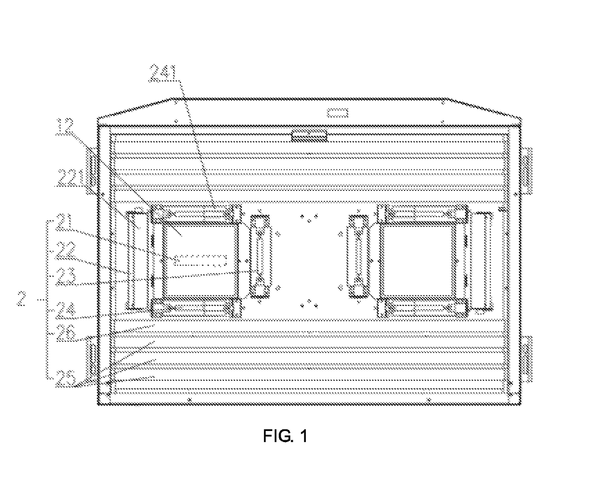
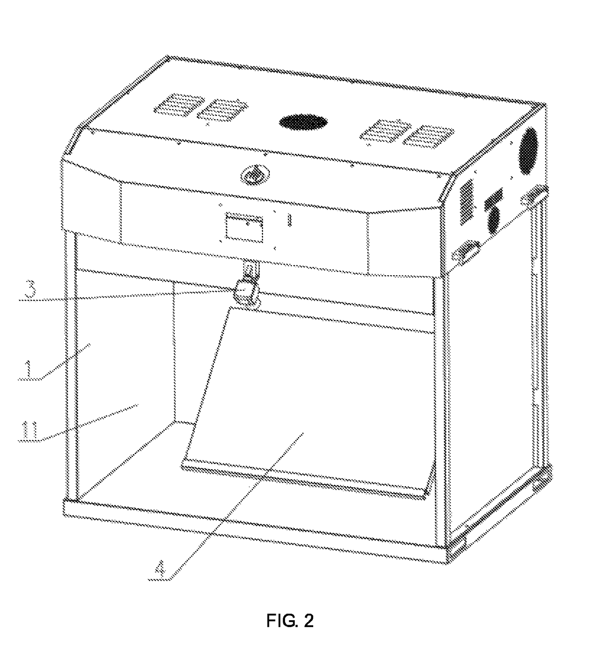
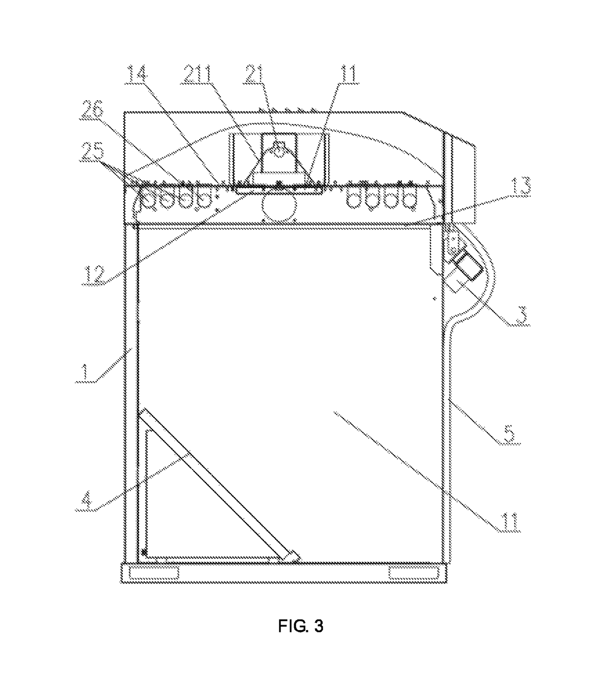
[0029]As shown in FIGS. 1, 2, 3, 4, 5, 6, 7, and 8, a specific embodiment of the standard light source color matching observation box of the present invention is shown. This embodiment comprises a box body 1, wherein the box body 1 has an opening at one side and forms an observation chamber 11 in the interior space, the top of the observation chamber 11 is provided with a standard light source 2, wherein the standard light source 2 comprises a halogen tungsten lamp 21, a light filter 12 is provided in the lower part of the halogen tungsten lamp 21, the top of the observation chamber 11 is further provided with a narrow-wave LED light source 22, the narrow band of the narrow-wave LED light source 22 is in the range of 350 nm to 850 nm, the halogen tungsten lamp 21 emits a light ray through the light filter 12 to be mixed with the light ray of the na...


PUM


Abstract

A standard light source color matching observation box comprises a box body, the interior space of which forms an observation chamber. The top of the observation chamber is provided with a standard light source comprising a halogen tungsten lamp under which a light filter is provided. The top of the observation chamber is further provided with an LED light. The halogen tungsten lamp emits a light ray through the light filter to be mixed with the light ray of the LED light. The illumination energy provided by a narrow-wave LED light source occupies 20% or less of the total radiation energy. The quality of the compensated light source of the invention is lower than <0.2 A level according to the metamerism index specified by D illuminant of the CIE standard. An object to be measured undergoes a color measurement by the compensated light ray to ensure accuracy of long-time color measurement.

Description

CROSS REFERENCE TO RELATED APPLICATIONS[0001]The present application is the US national stage of International Patent Application PCT / CN2016 / 079510 filed on Apr. 15, 2016, which, in turn, claims priority to Chinese Patent Application CN 201610123958.9 filed on Mar. 4, 2016.TECHNICAL FIELD[0002]The present invention relates to a detection structure, and more particularly to a standard light source color matching observation box.BACKGROUND ART[0003]The light source of the daylight of a standard D illuminant for a standard light source color matching observation box or light box in the current market includes a variety of brands of fluorescent tubes and uses a halogen tungsten lamp to pass through the light filter so that the radiated light ray simulates a D illuminant specified by the CIE standard. The relative spectral power distribution of the radiated light source passing through the light filter with the halogen tungsten lamp can reach A level of the metamerism index of the D illu...

Claims


Application Information

Patent Timeline
Patent Type & Authority Patents(United States)
IPC IPC(8): G01J3/46G01J3/10
CPCG01J3/10G01J3/46G01J3/0237G01J3/50G01J2003/102G01J2003/466
Inventor QIU, JIAYICUI, GUIHUALI, CHANGJUNZHAN, YINGSHENGLIN, JIANDENG, DAPING
Owner WENZHOU JIAYI INSTR
Why Eureka
Try Eureka