Check patentability & draft patents in minutes with Patsnap Eureka AI!

Conductive ink composition and conductive architecture for wireless antenna

a technology of conductive cage and conductive ink, which is applied in the direction of inks, antenna details, antennas, etc., can solve the problems of high cost and poisonous pollution, restrict the choice of substrates and applications, and reduce so as to achieve the effect of reducing the content of metallic filler and high conductivity

Active Publication Date: 2019-03-19
LAI CHUNG PING
View PDF9 Cites 2 Cited by
  • Summary
  • Abstract
  • Description
  • Claims
  • Application Information

AI Technical Summary

Benefits of technology

The binder-free conductive ink achieves high conductivity and improved adhesion without the need for polymer binders, reducing metal content and eliminating high-temperature sintering, while maintaining low resistance and wide substrate compatibility.

Problems solved by technology

Conductive inks for printing process like screen printing and inkjet printing are so expensive that the utilization of printing process cannot prevail over metal-etching process that result in high cost and poisonous pollution.
How to cut down on the metal amount and still maintain the resistance is the key issue.
On the other hand, high sintering temperature of metals often confines the choices of substrates and application.
The process is not only expensive but also produces many high-pollution wastes.
In addition, etching process also confines the choices of substrates.
The conductive inks in printing process are very expensive, and may suffer from poor stability or limited life time.
Compared to carbon species, metallic conductors are both high-priced and have potential oxidation problems.

Method used


Image

  • Conductive ink composition and conductive architecture for wireless antenna
  • Conductive ink composition and conductive architecture for wireless antenna

Examples


example 1

Binder-contained Conductive Ink

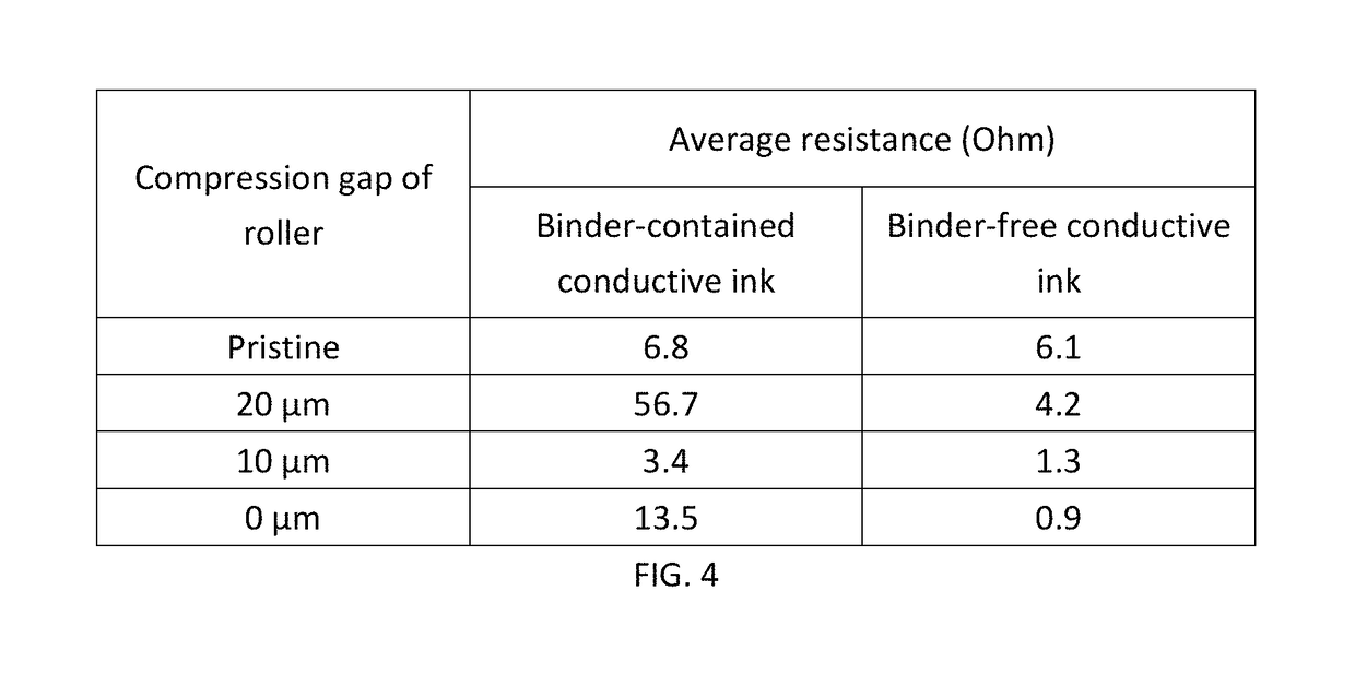
[0039]Here the composition of binder-contained conductive ink is a common composition, which consists of 10% acrylic binder, 50% Ag powders, 8% graphene powders, 2% other additives, and 30% solvent. A line pattern with 40 mm in length and 2 mm in width was used to print the conductive line. The ink performance was evaluated by the two-side resistance of printed conductive line. The resistance before and after compression is shown as FIG. 4.

example 2

Binder-free Conductive Ink

[0040]Here we removed the 10% acrylic binder from the binder-contained conductive ink shown in Example 1 to form a binder-free conductive ink. So the composition of binder-free conductive ink consists of 56% Ag powders, 9% graphene powders, 2% other additives, and 33% solvent. A line pattern with 40 mm in length and 2 mm in width was used to print the conductive line for test. The resistance before and after compression is shown as FIG. 4.

[0041]From FIG. 4, one can find that resistance of conductive line printed by binder-contained and binder-free conductive ink is similar before rolling compression. However, the adhesion of conductive line printed by binder-free ink is not good enough for the further application. So a further compression is applied to improve the adhesion and resistance of conductive line printed by binder-free ink. However, the resistance of conductive line printed by binder-contained ink increased 8.3 times after rolling at a 20 μm gap o...


PUM

PropertyMeasurementUnit
grain sizeaaaaaaaaaa

Abstract

A binder-free conductive ink with a conductive cage architecture for the wireless antenna with adhesion enhancement by carbon powders that aims to enormously reduce the solid content of conductor and can be used to print antennas. For example, silver content of the ink composition is greatly decreased due to the absence of insulated binder. Carbon powders (such as graphene nanoplatelets) are added as a conductive “cage” to reduce the use of insulated binder and significantly improve the conductivity of ink under low addition of conductor. Compression after printing is an innovative finding that not only improves the adhesion of a binder-free conductive ink with a conductive cage architecture but also enhances its conductivity. Such effects are credited to excellent contact between interfaces of particles and substrate. The unique recipe and process save printing from high-temperature sintering, further reducing processing cost and widening applicable substrates.

Description

[0001]This application is a Continuation-in-Part of application Ser. No. 14 / 599,562, filed Jan. 19, 2015.BACKGROUND OF THE INVENTION[0002]Field of the Invention[0003]The present invention relates to a binder-free conductive ink composition, conductive cage architecture, and fabrication process for wireless antenna which decreases its metallic filler content of conductive ink but still maintains high conductivity.[0004]Description of the Prior Art[0005]Conductive inks for printing process like screen printing and inkjet printing are so expensive that the utilization of printing process cannot prevail over metal-etching process that result in high cost and poisonous pollution.[0006]Metals like silver, nickel and copper as the conductive materials are the key reason why the price of conductive ink remains very high. How to cut down on the metal amount and still maintain the resistance is the key issue.[0007]On the other hand, high sintering temperature of metals often confines the choi...

Claims


Application Information

Patent Timeline
Patent Type & Authority Patents(United States)
IPC IPC(8): C09D11/52H01Q1/36C09D11/037H01Q1/38
CPCC09D11/52H01Q1/368C09D11/037H01Q1/38
Inventor LAI, CHUNG-PING
Owner LAI CHUNG PING
Features
  • R&D
  • Intellectual Property
  • Life Sciences
  • Materials
  • Tech Scout
  • Unparalleled Data Quality
  • Higher Quality Content
  • 60% Fewer Hallucinations
Learn More