Precise infrastructure mapping using full-waveform inversion of ground penetrating radar signals

a technology of infrastructure mapping and full-waveform inversion, applied in the field of ground penetrating radar, can solve the problems of increasing the risk of damaging existing utilities, insufficient information for simply detecting pipes at a given location, and insufficient records, so as to achieve accurate characteristic data and accurate estimate of the size of underground objects.

Active Publication Date: 2019-03-19
UNIV OF SOUTH FLORIDA
View PDF6 Cites 21 Cited by
  • Summary
  • Abstract
  • Description
  • Claims
  • Application Information

AI Technical Summary

Benefits of technology

[0026]An object of the invention is to provide a system and method adapted to more accurately estimate an underground object's size (e.g. diameter) and infilling material than is possible using only arrival times

Problems solved by technology
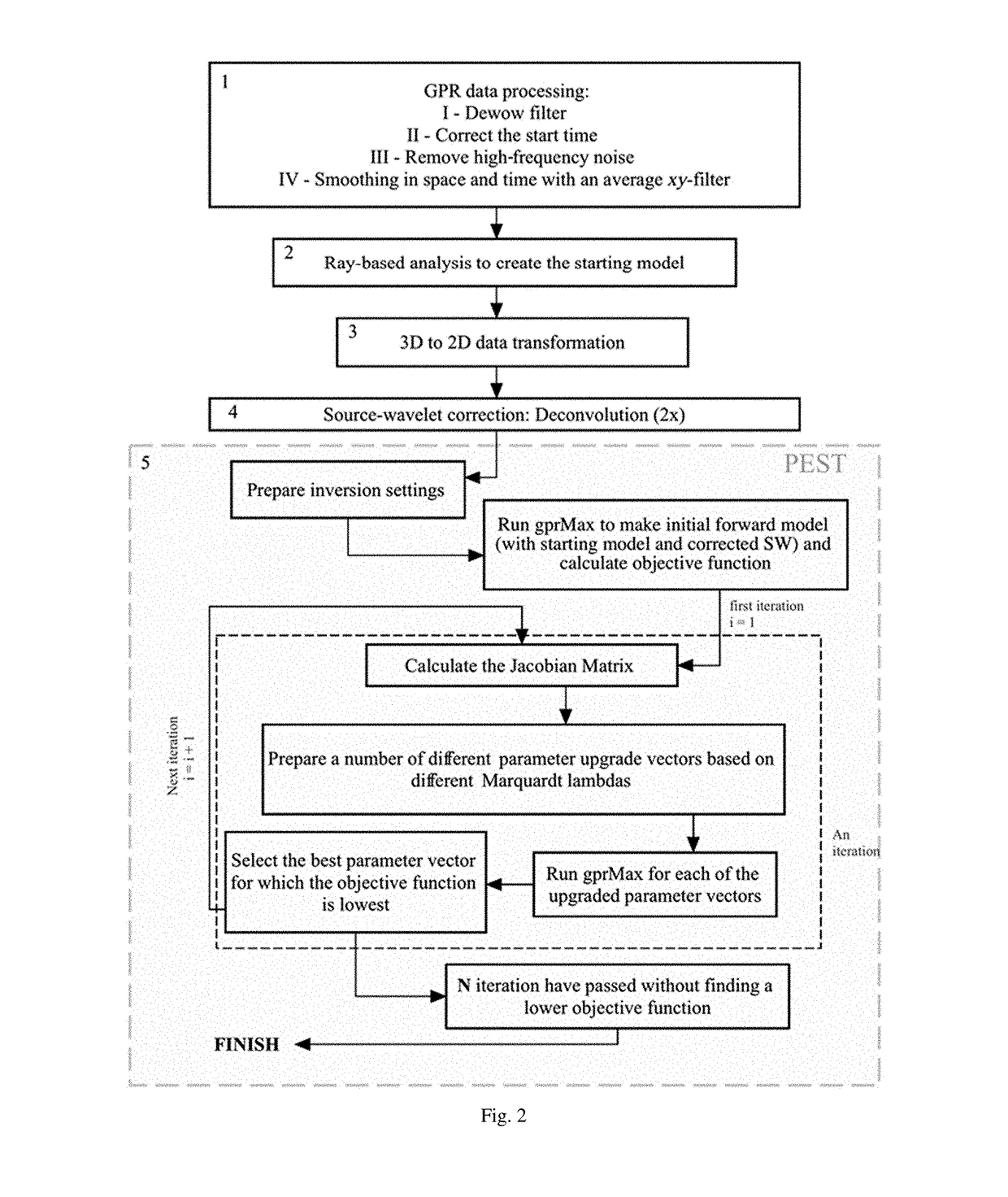
Civil engineering and construction industries face the challenge of maintaining and repairing existing pipelines as well as laying new pipes.
Increasing demand for new buried utilities increases the risk of damaging existing utilities (Lester and Bernold, 2007).
As infrastructure ages, the demand for repairs and replacement requires knowledge of the locations and connectivity of multiple utility systems installed at different times, using different materials, in increasingly dense networks, in which records are often incomplete.
In such scenarios, simply detecting a pipe at a given location may not be sufficient information.
However, Sham and Lai (2016) observe that the curve-fitting method is biased by human judgment.
When the pipe is narrow enough that the top and bottom returns overlap and interfere, extracting information on pipe diameter from the single hyperbola is challenging.
The hyperbola-fitting method also fails to provide any information about the pipe-filling material.
This method is handicapped because the variability in the GPR source wavelet (SW) and local complexities in the soil's permittivity and conductivity structure affect the shape of the returned pulse.
These perturba

Method used


Image

  • Precise infrastructure mapping using full-waveform inversion of ground penetrating radar signals
  • Precise infrastructure mapping using full-waveform inversion of ground penetrating radar signals
  • Precise infrastructure mapping using full-waveform inversion of ground penetrating radar signals

Examples


case study 1

[0110] Water-filled Pipe

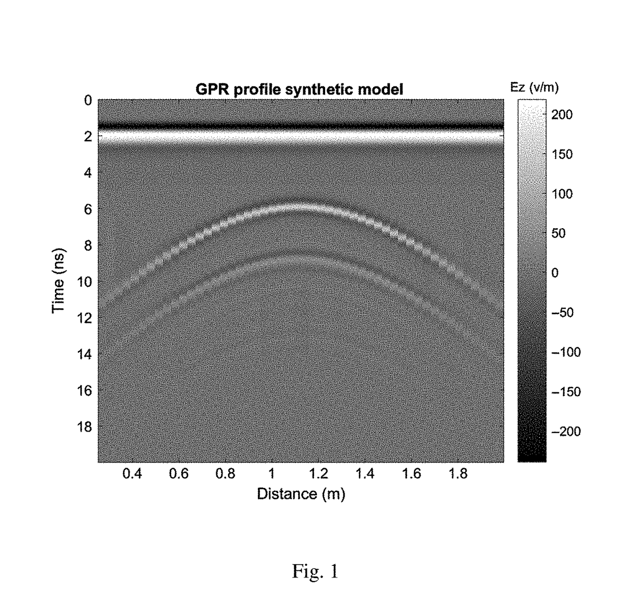
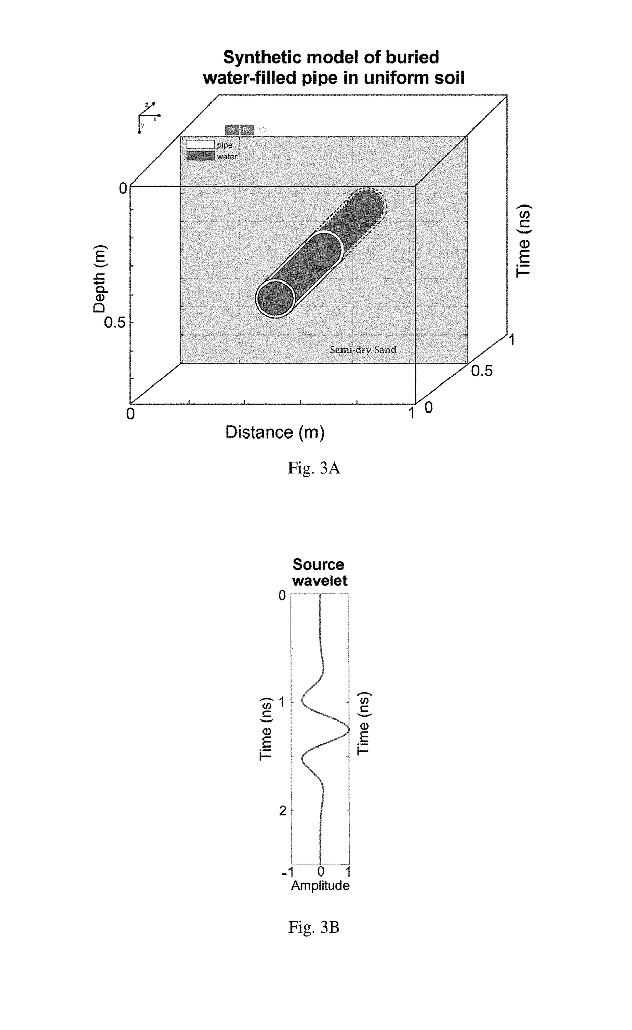
[0111]After the pipe was filled with water, as illustrated in FIG. 7, a grid of 15 parallel profiles was acquired, with 5 cm spacing between profiles (a subset is shown in FIG. 8). All profiles were run in a north-south direction, perpendicular to the pipe that was laid in an east-west direction. A Mala-ProEx system with 800 MHz shielded antennas was used. The spacing between traces along each profile was set to 8.5 mm and was controlled by an odometer wheel that was calibrated on site. The 80 traces centered on the hyperbola were selected to use in the inversion process. The water-filled pipe produced sharp hyperbolas in all the GPR profiles.

[0112]For a water-filled pipe, distinct reflections from the top and bottom of pipe are anticipated if the pipe diameter is greater than approximately half the radar wavelength. For this scenario, a wavelength of approximately 4 cm was expected; the pipe diameter of 7.6 cm is almost twice this value. Clear hyperbolas wer...

case study 2

[0123] Air-filled Pipe

[0124]On the same day that the pipe was buried, GPR profiles were collected using the 800 MHz antenna with the same settings as the previous section, but the pipe was empty. An air-filled pipe should produce weaker reflections and a shorter time gap between the upper and lower returns. Presumably, also the sand covering the pipe was less uniformly compacted and drier on the day of burial than six weeks later, and thus more “background noise” and a longer incoming wavelength was expected in this case. These factors combine to make the FWI in this case more challenging, designed to illustrate the efficiency of this technique in a more complex case.

[0125]A GPR profile (FIG. 13) was selected for the inversion procedure at the same location of the inverted profile in case study 1. Comparing FIGS. 9 and 13 illustrates the expected effects of water versus air and soil compaction. The air-filled pipe produces less pronounced and overlapping diffraction hyperbolas. Ther...


PUM


Abstract

A new method for FWI of common-offset GPR data, particularly targeting the dimensions and infilling material of buried pipes. The method is useful in situation where clear isolated diffraction hyperbolas indicate the presence of a pipe, but pipe dimensions and filling may be unknown. The invention is a method of taking GPR data and applying advanced numerical methods to get the depth and size of an underground pipe in a very accurate manner. An embodiment of the method consists of five main steps: GPR data processing, ray-based analysis to set a good initial model, 3D to 2D transformation of data, effective SW estimation, and FWI.

Description

BACKGROUND OF THE INVENTION[0001]1. Field of the Invention[0002]This invention relates, generally, to ground penetrating radar. More specifically, it relates to the use of full-waveform inversion to better estimate the characteristics of underground objects and media.[0003]2. Brief Description of the Prior Art[0004]Modern life depends on subsurface pipelines used to carry water, oil, gas, sewage, and other fluids. Civil engineering and construction industries face the challenge of maintaining and repairing existing pipelines as well as laying new pipes. Increasing demand for new buried utilities increases the risk of damaging existing utilities (Lester and Bernold, 2007). As infrastructure ages, the demand for repairs and replacement requires knowledge of the locations and connectivity of multiple utility systems installed at different times, using different materials, in increasingly dense networks, in which records are often incomplete. In such scenarios, simply detecting a pipe a...

Claims


Application Information

Patent Timeline
IPC IPC(8): G01S3/786G01S13/88G01S7/295G01S13/89
CPCG01S13/885G01S7/295G01S13/89G01S7/414
Inventor JAZAYERI, SAJADKRUSE, SARAH
Owner UNIV OF SOUTH FLORIDA
Why Eureka
Try Eureka