Method for producing a piston for an internal combustion engine

Active Publication Date: 2019-04-09
FEDERAL MOGUL NURNBERG GMBH
View PDF38 Cites 2 Cited by
  • Summary
  • Abstract
  • Description
  • Claims
  • Application Information

AI Technical Summary

Benefits of technology

[0010]In view of the regions in which a greater remelt depth is set, it is preferred at present to provide these in a plane which contains the axis of the piston pin. In particular, at present it is preferred to set the remelt depth at its greatest in this region and at its least in the direction perpendicular thereto, and to graduate the transitions between these points. The method according to the invention furthermore offers particular advantages with pistons having cooling channels, in part

Problems solved by technology

High thermal and mechanical loads on the piston result therefro

Method used


Image

  • Method for producing a piston for an internal combustion engine
  • Method for producing a piston for an internal combustion engine

Examples


Embodiment Construction

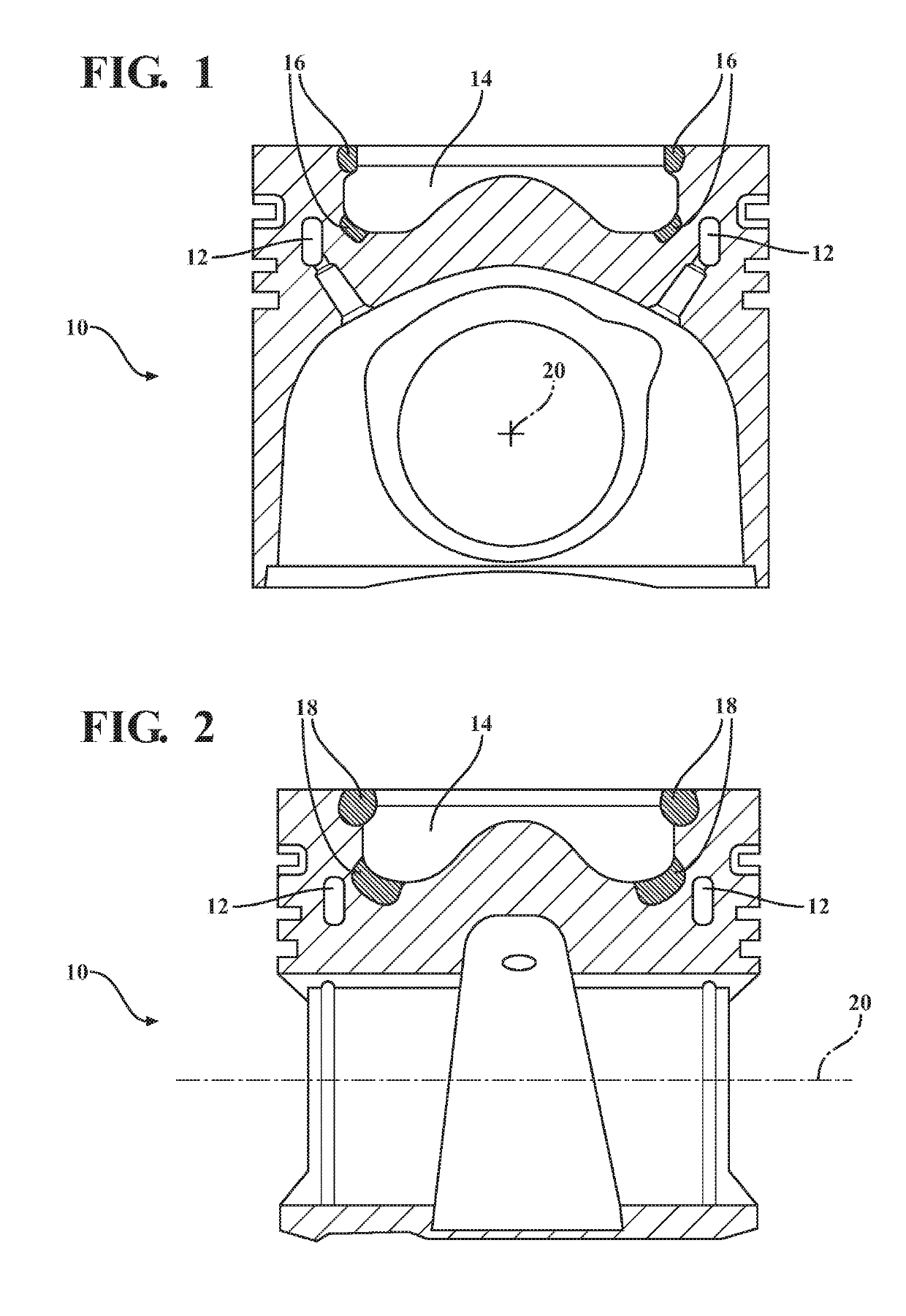
[0015]In FIG. 1, in a section perpendicular to the piston pin axis, a piston 10 is represented, which exemplarily comprises a cooling channel 12 and a combustion chamber cavity 14. With 16, those regions are indicated in which, to increase the loading capacity, a remelt treatment with a certain depth was performed.

[0016]In comparison with FIG. 2, it is shown that these regions 18 in the sectional plane, which contains the piston pin axis 20, are configured to be deeper. In other words, the remelted zone extends into deeper regions starting from the surface. By this, a particular loading capacity is achieved in the particularly loaded regions in the vicinity of the plane which contains the piston pin axis.

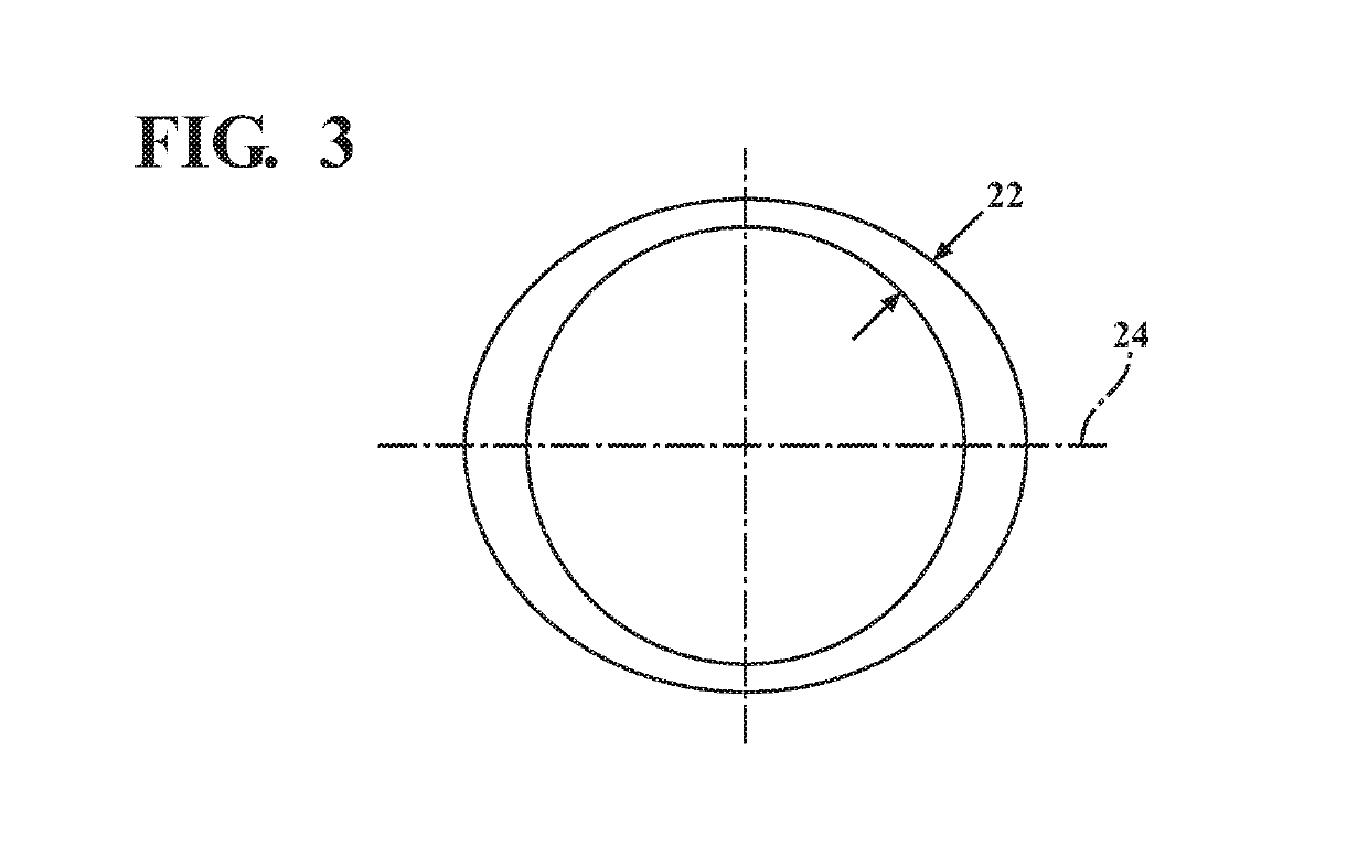
[0017]A preferred course of the remelt depth 22 along the circumference is evident from FIG. 3. The remelt depth 22 is, preferably in the region of the plane 24 which contains the piston pin axis, at the greatest and perpendicular thereto at the least, the transitions between said e...


PUM

PropertyMeasurementUnit
Depthaaaaaaaaaa

Abstract

In a method for producing a piston (10) for an internal combustion engine, a melt treatment is performed at least in regions in particular in the region of a combustion chamber depression (14), the depth of said melt treatment being varied in the circumferential direction.

Description

BACKGROUND OF THE INVENTION1. Technical Field[0001]The invention relates to a method for producing a piston for an internal combustion engine.2. Related Art[0002]The development of internal combustion engines is increasingly heading in the direction of smaller and yet higher-performance engines. High thermal and mechanical loads on the piston result therefrom, in particular in the region of the combustion chamber cavity.[0003]To increase the loading capacity in this region of a piston, it is known from DE 30 40 572 A1, for example, to subject regions of the combustion chamber cavity to a remelt treatment to refine the structure and increase resistance to thermal or mechanical changes.[0004]Similar methods are evident from DE 42 05 307 C1, JP 59-108849 A and CN 20 20 12408 U.SUMMARY OF THE INVENTION[0005]The invention is based on the object of improving, in view of efficiency while continuously fulfilling the requirements, a method for producing a piston for an internal combustion en...

Claims


Application Information

Patent Timeline
IPC IPC(8): B23K9/24B23P15/10B23K9/04F02F3/00F02F3/12C21D1/09F02F3/22
CPCB23K9/04B23P15/10F02F3/003F02F2200/04F02F3/12F02F3/22F02F2003/0061C21D1/09
Inventor LADES, KLAUSCROMME, WOLFRAM
Owner FEDERAL MOGUL NURNBERG GMBH
Why Eureka
Try Eureka