Variable volume transfer shuttle capsule and valve mechanism

a shuttle capsule and variable volume technology, applied in the field of split-cycle engines, can solve the problems of major efficiency loss and efficiency loss, and achieve the effects of reducing pressure energy loss, high sealing level, and durabl

Active Publication Date: 2019-04-09
TOUR ENGINE INC
View PDF62 Cites 1 Cited by
  • Summary
  • Abstract
  • Description
  • Claims
  • Application Information

AI Technical Summary

Benefits of technology

[0009]Disclosed herein are different and effective mechanisms to govern the transfer of working fluid in a timely manner and reduce pressure energy losses from the cold chamber to the hot chamber of a split-cycle engine. This may be achieved using a transfer shuttle capsule and valve system that may be durable with high level of sealing. The systems and methods described herein may separate the cold and hot cylinders with minimal “dead volume” between them, hence increasing the effective engine compression ratio and efficiency.
[0010]In view of the disadvantages inherent in the known types of external heat engines, embodiments disclosed herein include a Transfer Shuttle Capsule and Valve Mechanism (TSCVM) as part of an external heat engine (it could be also part of an internal combustion engine), which provides a more efficient utilization of temperature differentiated cylinders than conventional external heat engines (for example, various Stirling engine configurations). Some embodiments utilize a novel TSCVM for facilitating the efficient and reliable transfer of working fluid from the cold chamber to the hot chamber with minimal “dead volume” between them.
[0017]Decreasing the internal volume of the transfer chamber during transfer of the working fluid may advantageously increase the efficiency of the engine. For example, the decreasing volume may further increase the pressure of the working fluid prior to transfer, thus increasing the compression ratio of the engine. The engine may be an external split-cycle engine, and internal split-cycle engine, or any engine.
[0025]Decreasing the internal volume of the transfer chamber during transfer of the working fluid may advantageously increase the efficiency of the engine. For example, the decreasing volume may further increase the pressure of the working fluid prior to transfer, thus increasing the compression ratio of the engine. The engine may be an external split-cycle engine, and internal split-cycle engine, or any engine.
[0031]Decreasing the internal volume of the transfer chamber during transfer of the working fluid may advantageously increase the efficiency of the engine. For example, the decreasing volume may further increase the pressure of the working fluid prior to transfer, thus increasing the compression ratio of the engine. The engine may be an external split-cycle engine, and internal split-cycle engine, or any engine.

Problems solved by technology

The volume of this pipe, often regarded as “dead volume,” causes a major efficiency loss.
During the high pressure part of the cycle, hot air from the engine mixes with colder air in the dead volume, which leads to a loss in efficiency.

Method used


Image

  • Variable volume transfer shuttle capsule and valve mechanism
  • Variable volume transfer shuttle capsule and valve mechanism
  • Variable volume transfer shuttle capsule and valve mechanism

Examples


Embodiment Construction

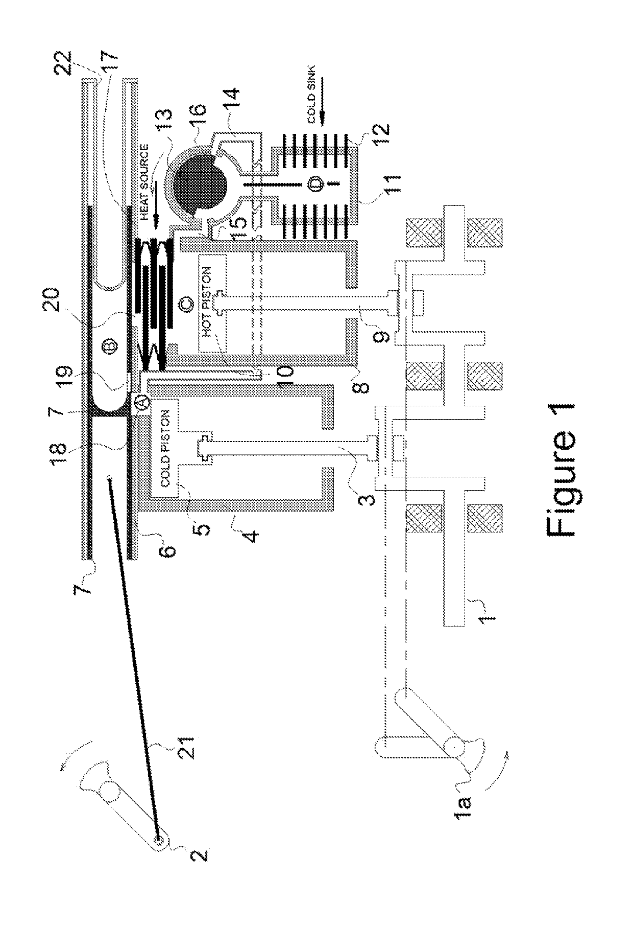
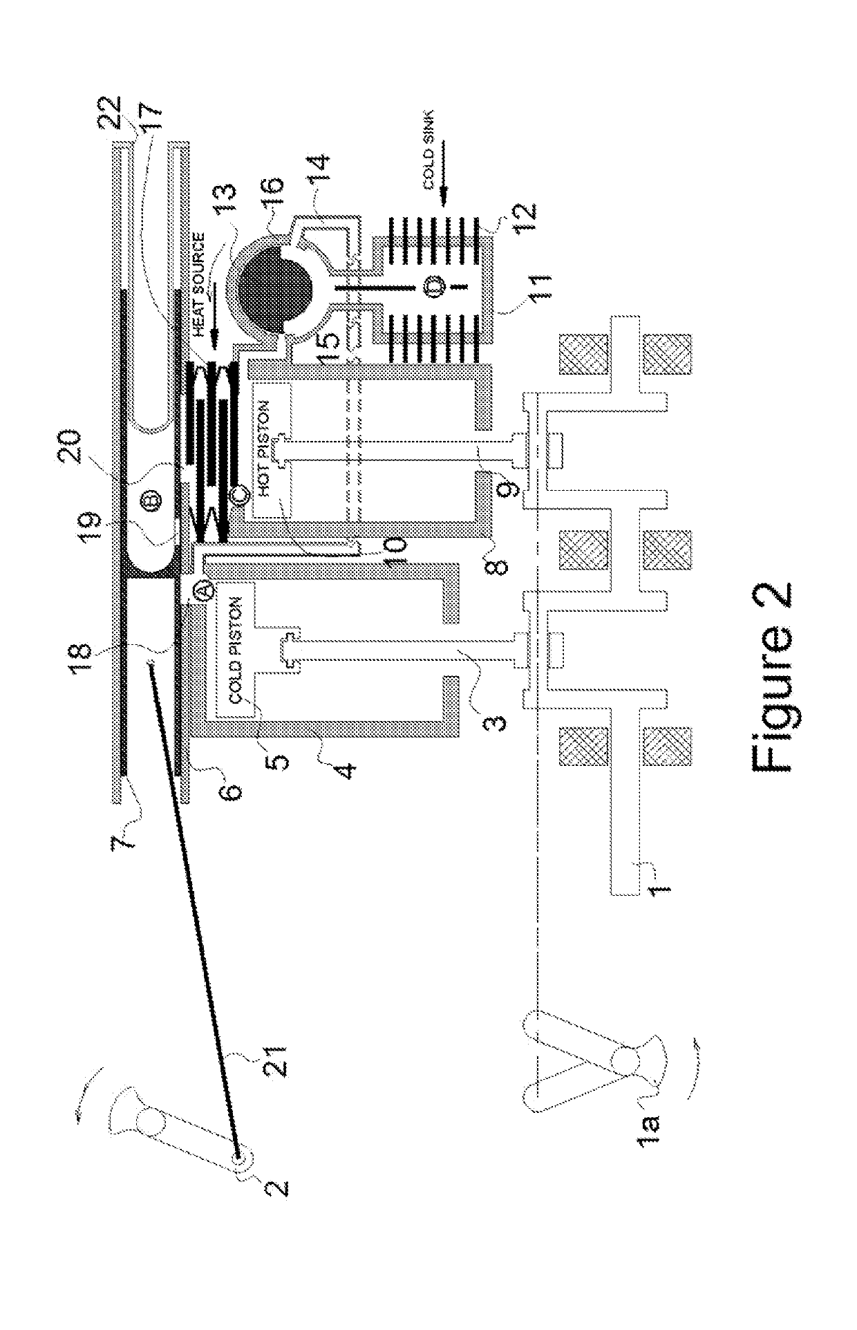
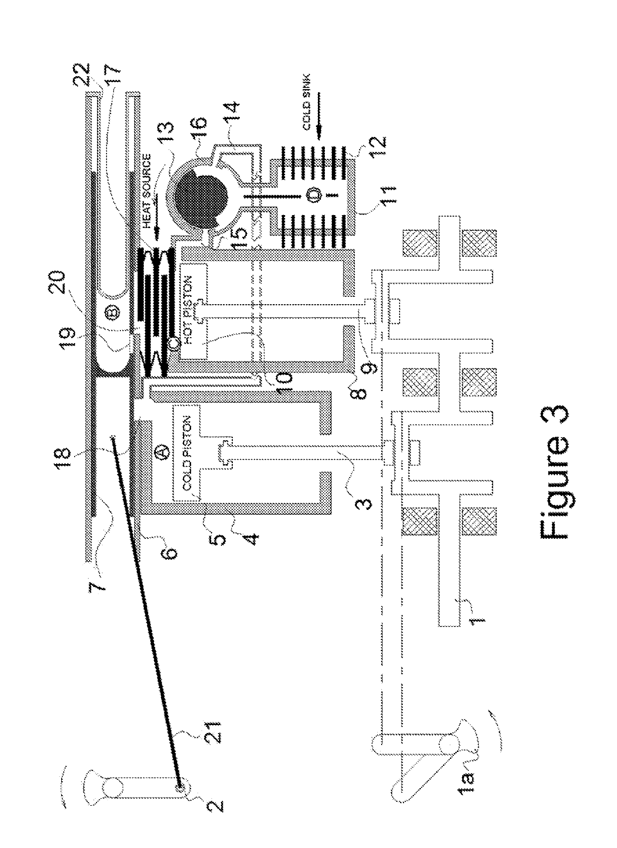
[0053]The invention is described in detail below with reference to the figures, wherein similar elements are referenced with similar numerals throughout. It is understood that the figures are not necessarily drawn to scale. Nor do they necessarily show all the details of the various exemplary embodiments illustrated. Rather, they merely show certain features and elements to provide an enabling description of the exemplary embodiments.

[0054]Referring to FIG. 1, in accordance with one embodiment, an in-line configuration of an external heat engine includes: a compression cylinder 4, an expansion cylinder 8, a compression piston 5, an expansion piston 10, a cold chamber A, and a hot chamber C. It also includes two piston connecting rods 3 and 9, and a crankshaft 1 that actuate the pistons in the two cylinders.

[0055]Still referring to FIG. 1, the external heat engine also includes a TSCVM 7, a TSCVM cylinder 6, a transfer chamber B, which is located within the TSCVM 7, a TSCVM spool por...


PUM


Abstract

An engine includes a compression chamber that intakes and compresses working fluid; an expansion chamber that expands and exhausts working fluid; and a transfer chamber that receives working fluid from the compression chamber and transfers working fluid to the expansion chamber, wherein an internal volume of the transfer chamber decreases during the transfer of working fluid.

Description

CROSS-REFERENCE TO RELATED APPLICATIONS[0001]This application is a U.S. National Stage application of International Application No. PCT / US2015 / 011856, filed Jan. 16, 2015, which claims the benefit of U.S. Provisional Application No. 61 / 929,143, filed Jan. 20, 2014, the contents of which are incorporated herein by reference in their entiretiesBACKGROUND[0002]Field[0003]This disclosure relates to split-cycle engines incorporating numerous refinements and design features that may generally enhance engine performance. Particularly, this disclosure may increase split-cycle engine compression ratio. It may also raise working fluid temperature differentiation by providing cooler working fluid during the compression stroke, and hotter working fluid during the expansion stroke. Those improvements may be achieved by reducing dead volume usually residing within the various components of a split-cycle engine and connecting tube which serves as fluid connection passage between the compression cy...

Claims


Application Information

Patent Timeline
Patent Type & Authority Patents(United States)
IPC IPC(8): F01L5/04F02G1/055F02G1/043F02G1/02F01L5/06F01L7/02F01N5/02
CPCF02G1/055F01L5/04F01L5/06F01L7/02F01L7/022F02G1/043F02G1/02F02G2270/55F01N5/02F02G2244/00F02G2244/08F02B33/12F02B41/06
Inventor TOUR, HUGO BENJAMINTOUR, ODEDTOUR, GILADSIVAN, EHUDWAHL, MICHAEL H.
Owner TOUR ENGINE INC
Why Eureka
Try Eureka