
Motor control apparatus and electric power steering apparatus provided the same

a technology of motor control and electric steering, which is applied in the direction of electric motor control, electrical steering, transportation and packaging, etc., can solve the problems of motor release switch breaking or destroying, unexpected situation of system abnormality detection time, etc., and achieves the effect of enhancing steering safety and reliability, and cheap constitution

Inactive Publication Date: 2019-04-16
NSK LTD
View PDF22 Cites 5 Cited by
  • Summary
  • Abstract
  • Description
  • Claims
  • Application Information

AI Technical Summary

Benefits of technology

The present invention relates to a motor control apparatus and an electric power steering system. The technical effect of this invention is to securely and easily protect the semiconductor switching elements of the motor release-switch provided between the motor and the inverter, and to further enhance the improvement of the steering safety and the reliability. This is achieved without adding new device parts or a new protecting circuit, and by controlling the regenerative current to prevent damage to the motor release-switch during rotation. Additionally, the invention takes into account the temperature characteristic of the motor release-switch for increased safety and reliability.

Problems solved by technology

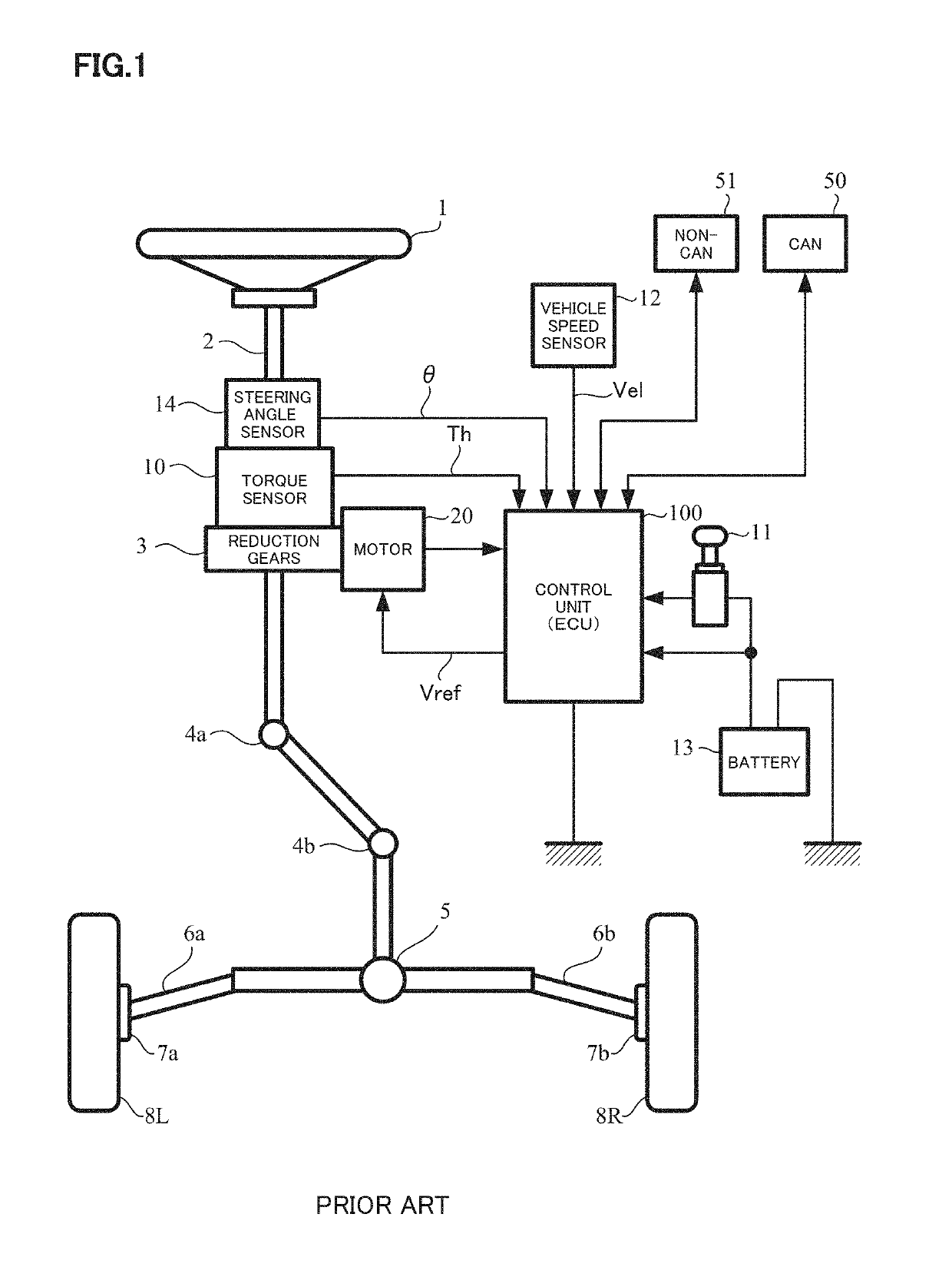
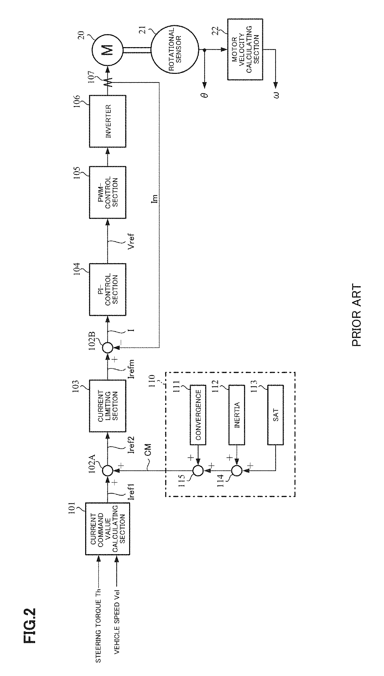
In such the above electric power steering apparatus, there are cases to encounter an unexpected situation of a system abnormality detection time (for example, a disconnection of the torque sensor, a short-circuit accident of the motor control stage-FETs and so on).
But, when the assist continuation becomes impossible due to the system abnormality, the motor is rotated even if the inverter is stopped.
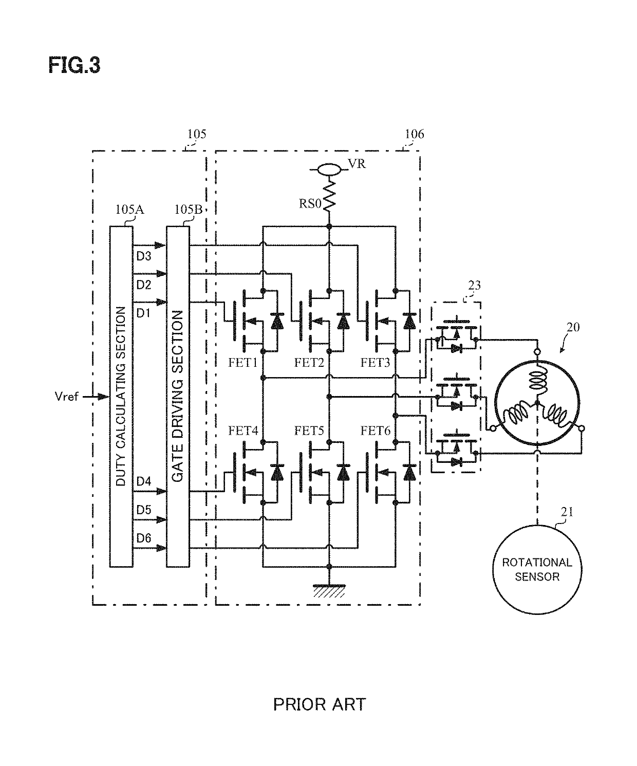
At this time, if the motor release-switch is OFF-switched during the motor rotation, a regenerative current of the motor deviates an area of safety operation of the motor release-switch and there is a case that the motor release-switch is broken or destroyed.

Method used


Image

  • Motor control apparatus and electric power steering apparatus provided the same
  • Motor control apparatus and electric power steering apparatus provided the same
  • Motor control apparatus and electric power steering apparatus provided the same

Examples


first embodiment

[0048]In such a constitution, an operation example of the present invention (the first embodiment) will be described with reference to a flow chart of FIG. 6.

[0049]When the control operation is started, first the motor release-switch 140 (140U, 140V, 140W) is ON-switched by the motor release-switch control section 133 through the control section 120 (Step S1). The state detecting section 125 judges whether the abnormality is detected in the sensor abnormality detecting section 131 or the inverter abnormality detecting section 135 or not (Step S2), and ON-switches the control of the inverter 106 by the current control section 124 in the control section 120 when the abnormality is not detected (Step S3). Thereafter, a next control is repeated.

[0050]Further, in a case that the abnormality is detected at the above Step S2, it is judged that the continuation of the assist control is impossible, and the control of the inverter 106 is OFF-switched by the control section 120 (Step S4). The ...

second embodiment

[0056]Next, the second embodiment considered a temperature of the semiconductor switching element or circumference temperature will be described.

[0057]Generally, the area of safety operation (AOS) of operating FET is defined by a relation of a drain current Id and a drain-source voltage Vds as shown in FIG. 7 and a temperature characteristic of the maximum allowable loss Pd as shown in FIG. 8. However, the area of safety operation varies due to operating conditions (an FET-case temperature Tc, an operating frequency f, an ON-width and so on) actually used. Especially, since the maximum allowable loss Pd decreases when the case temperature increases, the temperature information is important in order to obtain an exact the area of safety operation. Since it is possible to estimate the case temperature Tc of the FET if capable of knowing a temperature due to a temperature detecting element on a power substrate, it is possible to calculate the maximum allowable loss Pd corresponding to ...


PUM


Abstract

An electric power steering apparatus that drive-controls a motor by an inverter, and a motor release-switch is connected between the inverter and the motor, comprising: a control section to detect an assist state on a driving control system and to ON / OFF-switch a control of the inverter based on a detection result; a motor rotational number detecting section to detect a rotational number of the motor; an energy calculating section to calculate an energy of a motor back-EMF and a regenerative current based on the rotational number; and a judging section to compare the energy with an area of safety operation of the motor release-switch and to OFF-switch the d motor release-switch when the energy becomes within the area of safety operation. As occasion demands, the area of safety operation is calculated with the temperature.

Description

CROSS REFERENCE TO RELATED APPLICATIONS[0001]This application is a National Stage of International Application No. PCT / JP2015 / 063329 filed May 8, 2015, claiming priority based on Japanese Patent Application No. 2014-122283 filed Jun. 13, 2014 and Japanese Patent Application No. 2015-042718 filed Mar. 4, 2015, the contents of all of which are incorporated herein by reference in their entirety.TECHNICAL FIELD[0002]The present invention relates to a motor control apparatus that protects a motor release-switch comprising semiconductor switching elements (e.g. FETs) and being connected to a power supplying section (an inverter) from a regenerative power (obtained with a back-EMF and a regenerative current) energy (power) (and a temperature) caused by a motor rotation when a motor is rotated by an external force, and to an electric power steering apparatus provided the above motor control apparatus.[0003]The electric power steering apparatus applies an assist force to a steering system of...

Claims


Application Information

Patent Timeline
Patent Type & Authority Patents(United States)
IPC IPC(8): H02P29/68B62D5/04H02P27/08
CPCB62D5/0484B62D5/046B62D5/0496H02P29/68B62D5/0481H02P27/08
Inventor SHINKAWA, NAOTOFUKINUKI, SHIGERUKUMAGAI, SHINSHIMAKAWA, SHIGERUKOGURE, TERUYOSHI
Owner NSK LTD
Learn More