Asymmetric separator for secondary battery
a secondary battery and asymmetric separator technology, applied in the manufacture of final products, cell components, cell component details, etc., can solve the problems of battery short circuit, low thermal stability limit, and inability to meet the requirements of us
- Summary
- Abstract
- Description
- Claims
- Application Information
AI Technical Summary
Benefits of technology
Problems solved by technology
Method used
Image

Examples
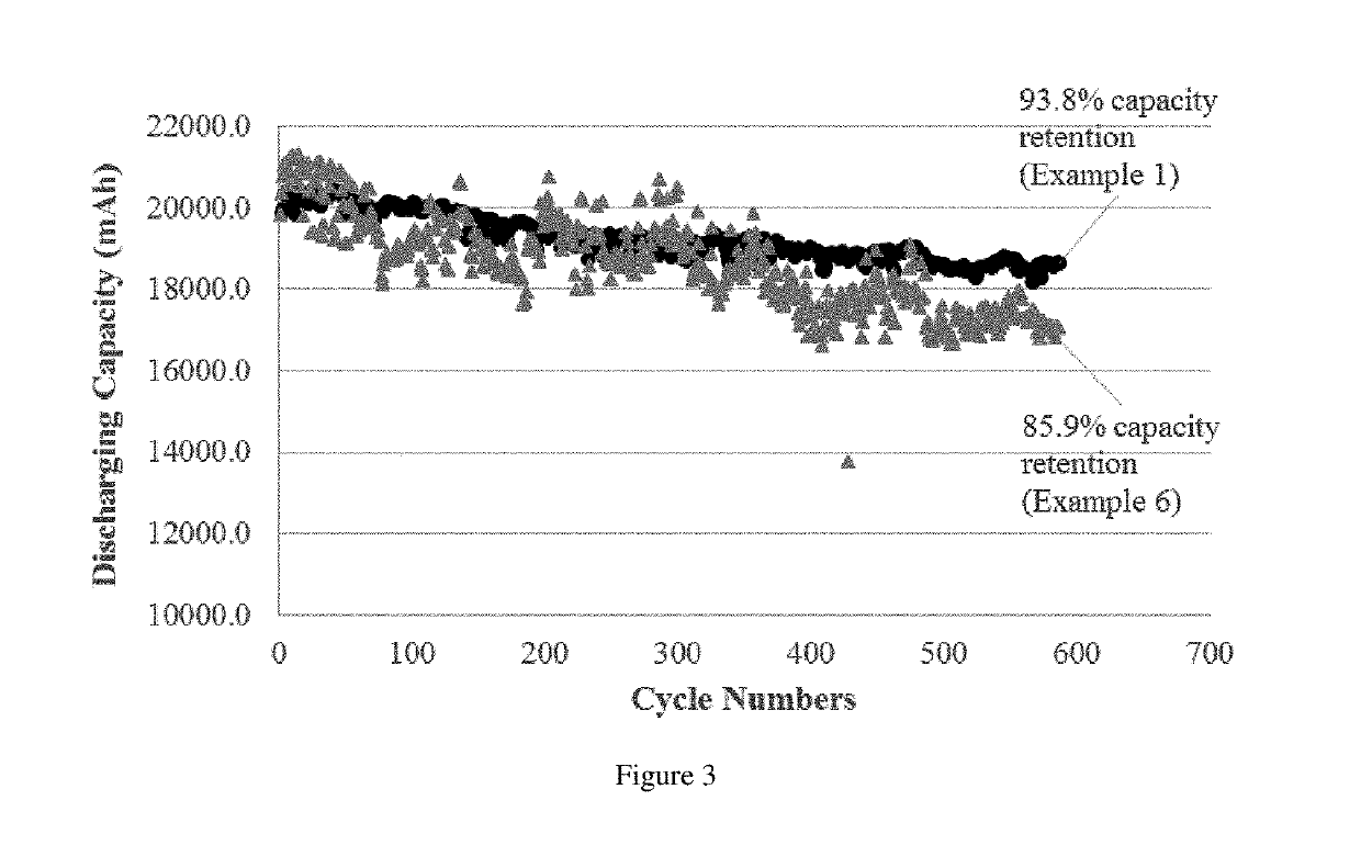
example 1
[0171]A first aqueous binder solution was prepared by dissolving 20 g of carboxymethyl cellulose (CMC) (obtained from DAICEL Corporation, Japan; product no. CMC1390) in 3.35 L de-ionized water. To the first aqueous binder solution were added 50 g of K2TiO3 whiskers (obtained from Shanghai Dian Yang Industry Co. LTD, China) and 3 g of styrene butadiene rubber (SBR) (obtained from NIPPON A&L INC., Japan; product no. AL-2001). The whiskers had an average diameter of 0.5 μm and an average length of 4 μm. After the addition, the suspension was stirred for 30 minutes at room temperature at a stirring speed of 50 rpm (revolution per minute) to form a first slurry.
[0172]A second aqueous binder solution was prepared by dissolving 30 g of CMC in 3.2 L de-ionized water. To the second aqueous binder solution were added 60 g of Al2O3 particles (obtained from Taimei Chemicals Co. Ltd., Japan; product no. TM-100) and 4 g of SBR. The particles had an average diameter of 8 μm. After the addition, th...
example 2
[0174]A first aqueous binder solution was prepared by dissolving 20 g of CMC in 3.35 L de-ionized water. To the first aqueous binder solution were added 55 g of K2Ti6O13 whiskers (obtained from Shanghai Dian Yang Industry Co. LTD, China) and 3 g of SBR. The whiskers had an average diameter of 2 μm and an average length of 20 μm. After the addition, the suspension was stirred for 30 minutes at room temperature at a stirring speed of 50 rpm to form a first slurry.
[0175]A second aqueous binder solution was prepared by dissolving 30 g of CMC in 3.2 L de-ionized water. To the second aqueous binder solution were added 45 g of SiO2 particles (obtained from Sigma-Aldrich, US; product no. S5631) and 4 g of SBR. The particles had an average diameter of 3 μm. After the addition, the suspension was stirred for 30 minutes at room temperature at a stirring speed of 50 rpm to form a second slurry.
[0176]A 30 cm wide nonwoven PET fabric (obtained from MITSUBISHI PAPER MILLS LTD, Japan) having a thic...
example 3
[0177]A first aqueous binder solution was prepared by dissolving 55 g of CMC in 6.55 L de-ionized water. To the first aqueous binder solution were added 50 g of Al2O3 particles (obtained from Taimei Chemicals Co. Ltd., Japan; product no. TM-100), 65 g of K2TiO3 whiskers (obtained from Shanghai Dian Yang Industry Co. LTD, China), and 8.0 g of SBR. The particles had an average diameter of 6 μm. The whiskers had an average diameter of 0.6 μm and an average length of 12 μm. After the addition, the suspension was stirred for 60 minutes at room temperature at a stirring speed of 50 rpm to form a first slurry.
[0178]A second aqueous binder solution was prepared by dissolving 30 g of CMC in 3.2 L de-ionized water. To the second aqueous binder solution were added 60 g of ZrO2 particles (obtained from Shanghai Dian Yang Industry Co. LTD, China; product no. ZR-25(M)) and 4 g of SBR. The particles had an average diameter of 3 μm. After the addition, the suspension was stirred for 30 minutes at r...
PUM
| Property | Measurement | Unit |
|---|---|---|
| length | aaaaa | aaaaa |
| diameter | aaaaa | aaaaa |
| diameter | aaaaa | aaaaa |
Abstract
Description
Claims
Application Information