Defense related robotic systems

a robotic system and defense technology, applied in the field of robotic systems, can solve the problems of inability to meet the needs of a wide range of tasks, interfere with time constraints, and waste of resources, and achieve the effect of reducing the moment of inertia

Inactive Publication Date: 2019-04-30
RE2
View PDF89 Cites 6 Cited by
  • Summary
  • Abstract
  • Description
  • Claims
  • Application Information

AI Technical Summary

Benefits of technology

[0015]A further object of the invention is to provide a quick-release assembly including a first joint member, having a cylindrical body, and a robot component mounted thereon, the first joint member having a first mechanical coupler and a second joint member, having a cylindrical body, a robot arm mounted thereon, the second joint member having a stick and power assembly, the stick having a second coupler, where the first coupler is coaxially aligned with the second coupler and pressed into the second coupler, and the first coupler is detachably connected to the second coupler for transferring power across the quick-release assembly. The power assembly is placed in a proximal end of the second joint member to reduce the moment of inertia. The robot component can receive all mechanical power from the driveshaft or can have an additional electrical connector, the additional electrical connector supplying power source to activate the robot component. The assembly can include more than one source of power for tools having need, further including a mechanical power assembly, the power assembly supplying a second power source to a robot component.
[0016]The present invention includes a method for connecting a robotic tool to a robotic arm, including the following steps of providing a quick-release coupling assembly including a first joint member mounted on a robot component having a first coupler and a second joint member mounted on a robot arm having a second coupler, a clamp, and a collar, wherein the first coupler is connected to the second coupler, the first coupler has at least one member extending radially outward circumferentially spaced on a first end of the first coupler from an end of the first coupler, the clamp having a first member on a first end, fingers extending inward and spaced circumferentially around the clamp on a second end, and an externally threaded surface, the fingers having an outside slanted surface and a first inside slanted surface and second inside slanted surface, and second coupler having a cylindrical body defining a ring having a slanted surface, and having at least one member extending radially outward and having a slanted surface at an, end adjacent the ring, the collar having a cylindrical body with an axial bore defining an inwardly slanted surface on a first end and an internally threaded portion at a second end thereon. Pushing notches on a female coupler onto bosses in the male coupler displacing a male coupler into the clamp; rotating the locking collar, thereby turning the locking collar and the clamp as one unit and rotating the fingers directly over the member of the male coupler; aligning a sequencing guide and a sequencing pin to lock the clamp to the female coupler and releasing it from the locking collar; moving coaxially the clamp into engagement with the locking collar by rotation of multi-thread of locking collar into a multi-thread of the clamp, threadably moving the fingers inward in a first stage wedge; and pushing inward, the fingers on the members of the second coupler, thereby causing a second stage wedge, causing the clamp to move down relative to the first coupler.

Problems solved by technology

However, in certain areas such as military or civilian Explosives Ordinance Disposal (EOD), this process is too time-consuming and interferes with the time constraints imposed by their urgent mission.
However, some tools may require additional motors, processors, or sensors so connections for electrical power and electrical control signals are also required.
This has resulted in a proliferation of small UGVs, each performing admirably on tasks within each of its subset of core competencies, but is generally unsuitable for tasks that vary too widely from its essential purpose.
It is impractical to expect field teams to carry multiple UGVs, each suited for a specific task.
This reduces the ability of the operator to capitalize on the experience and intuition gained from operating previous robots, because the operator cannot rely on the trained reflexes developed while controlling previous robots.
In fact, these differing control schemes lead to operator errors and inefficient control.
Another approach has been to design new, more capable robots, but this approach has drawbacks because even if a robot were designed and built to perform all of the tasks currently assigned to UGVs, it would quickly become outdated as new tasks and jobs are identified.
Additionally, external variables, such as physical environment, make UGVs designed for one environment wholly impractical for use in another environment, meaning a number of new robot types would need to be designed, tested, and built.

Method used


Image

  • Defense related robotic systems
  • Defense related robotic systems
  • Defense related robotic systems

Examples


Embodiment Construction

[0035]The object of the present invention is to provide a quick-release assembly for quickly separating tools and effectors mechanically from their manipulator arms, thus allowing easy integration of future tools and effectors as the complexity of the system is contained in the manipulator arms. It is still a further object to make the tools essentially simple line replaceable units that can be easily replaced when they fail.

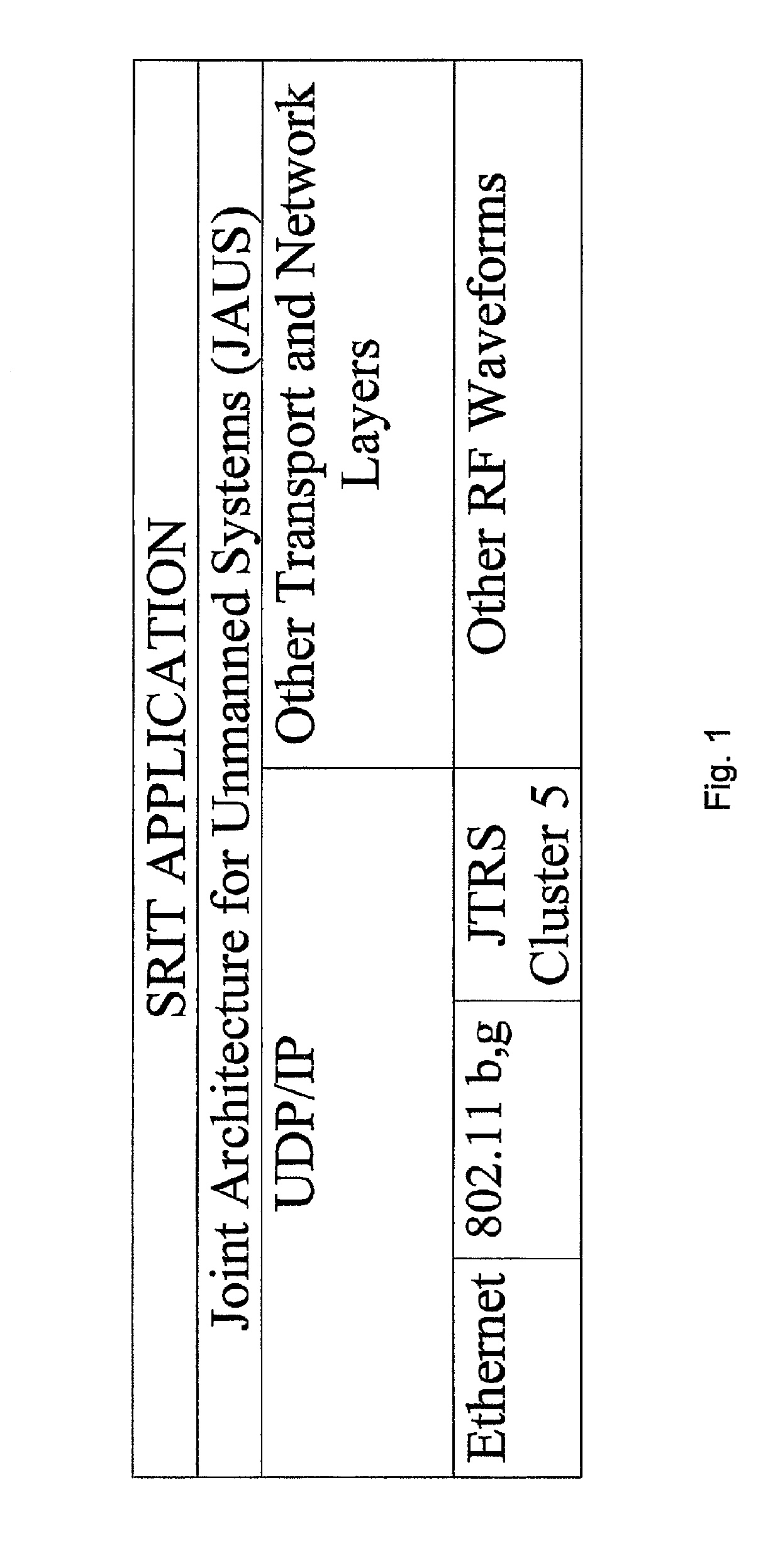
[0036]The quick-release assembly provides a connection easily connected and disconnected having full pass through power, electrical, and signal capabilities. The present invention utilizes a modular software approach, shown in FIG. 1. Using the stack analogy, at the bottom of the software stack, communication is accomplished by UDP / IP and others such as by Ethernet 802.11b,g, and the Joint Tactical Radio System (JTRS) cluster 5 or other RF wave forms. The Joint Architecture for Unmanned Systems (JAUS) layer relies on these transport and network layers for commun...


PUM


Abstract

A robot quick-release assembly has a first joint member and a robot component mounted thereon, the first joint member has a first coupler and a second joint member, a robot arm mounted thereon, has a second coupler, a clamp, and a locking collar. The first coupler can be coaxially aligned with the second coupler and pressed into the second joint member, and detachably connected to the second joint member. The first mechanical coupler is detachably connected to the second mechanical coupler for transferring power across the quick-release assembly. The robot component can receive an additional electrical connector, the additional electrical connector supplying power to the robot component. The quick-release assembly coupling assembly further exerts large forces with the application of a relatively small torque to the locking collar by applying a two stage wedge engagement and can further include a sequencing system.

Description

CROSS REFERENCE TO RELATED APPLICATIONS[0001]This application is a divisional application of U.S. patent application Ser. No. 12 / 167,735, filed Jul. 3, 2008 and entitled “Defense Related Robotic Systems”, which claims priority to Provisional U.S. Application No. 60 / 958,405, filed on Jul. 5, 2007 and entitled “Defense Related Robotic Systems”, the disclosures of which are hereby incorporated by reference in their entirety.BACKGROUND OF THE INVENTIONField of the Invention[0002]This application relates to a robotic system having a movable robotic arm and, more specifically, to a robotic system having a movable robotic arm with a quick-release assembly for connecting a tool to the robotic arm.Description of the Related Art[0003]Robotic arms often require specialized configurations to accomplish their particular missions. Such configuration could involve changing the length of a link in the arm or attaching a different end effector or tool. (Henceforth, we will refer to making any of the...

Claims


Application Information

Patent Timeline
Patent Type & Authority Patents(United States)
IPC IPC(8): B25J15/04B25J19/00B25J13/08B25J17/00H01R13/625F16B7/20B23B31/113B25J19/04F16B21/04B23B31/11
CPCB25J15/0408B23B31/113B25J13/08B25J15/04B25J15/045B25J15/0483B25J17/00B25J19/0029B25J19/04F16B7/20F16B21/04H01R13/625B23B31/11Y10T403/18Y10S901/28Y10T74/20329
Inventor PEDERSEN, JORGENEASUDES, JESSEGUNNETT, KEITH M.CULBERTSON, JOHNDAVISON, TIMOTHY
Owner RE2
Why Eureka
Try Eureka