Apparatus and method for performing passive sensing

a passive sensing and apparatus technology, applied in the direction of instruments, measurement devices, using reradiation, etc., can solve the problems of inability to determine whether surveillance is being performed, the receipt of direct transmitted signals is an unwanted and problematic component, and it is difficult to perform passive sensing in a real-time dynamic context, so as to reduce the cost and complicate the exploitation of other data

Inactive Publication Date: 2019-05-14
UCL BUSINESS PLC
View PDF21 Cites 0 Cited by
  • Summary
  • Abstract
  • Description
  • Claims
  • Application Information

AI Technical Summary

Benefits of technology

[0016]In some embodiments, wherein detecting and extracting portions of the reference signal includes splitting the reference signal into multiple successive segments of equal length; identifying portions of the reference signal such that data transmissions are present in the same time interval in each segment with respect to the start of that segment; and extracting the identified portions of the reference signals. Note that portions of the reference signal that do not fall into such intervals are discarded (even if they include data transmissions). This reduces the overall amount of data to be processed to facilitate real-time observations, and also imposes a regular time structure on the extracted portions (which can be exploited by further processing to determine any velocity offset).
[0018]Various embodiments of the invention utilise existing signals, such as W-Fi signals (IEEE 802.11) to detect and track moving targets via real-time passive sensing. The passive sensing can function both indoors and outdoors, including in highly cluttered environments, and is able to detect targets through walls. It can also operate in all weather conditions, and light levels. In addition, the ubiquitous nature of wireless communication networks allows the passive sensing to be deployed in a wide range of situations and also for a wide range of surveillance and monitoring applications.
[0020]Various embodiments described herein utilise a technique termed burst-specific processing in order to provide high speed signal processing of the received signals, thereby supporting real-time output of the passive sensing results. The burst-specific processing exploits the fact that for many wireless digital communication signals, the data is transmitted according to a known (predefined) structure. In particular, the burst-specific processing disclosed herein, for use in passive radar systems based on such wireless digital communication signals, helps to optimise the data sampling and subsequent cross-correlation processing of such transmissions based on the known structure.
[0021]The passive sensing exploits “signals of opportunity”, and so does not require a dedicated transmitter section. This results in a receiver-only system which is significantly lower in cost than a comparable active detection system. Furthermore, as the system does not transmit any signals, it is completely covert, and not subject to any spectrum license fees. An additional benefit is that it is does not rely upon obtaining any personal information, such as mobile telephone numbers, which can complicate the exploitation of other data (such as mobile telephone locations and device ID) due to privacy requirements.

Problems solved by technology

However, in passive sensing, the adversary is unable to determine that surveillance is being performed, since only the background radio transmissions (and their reflections) are present.
This receipt of the directly transmitted signal represents an unwanted and problematic component, and is often referred to as direct signal interference (DSI).
One difficulty with passive sensing is the need to search through the surveillance signal in both time and frequency (j and n respectively in equation 1 above) in order to locate any component(s) of the reference signal in the surveillance signal.
This can make it rather challenging to perform passive sensing in a real-time, dynamic context.

Method used


Image

  • Apparatus and method for performing passive sensing
  • Apparatus and method for performing passive sensing
  • Apparatus and method for performing passive sensing

Examples


Embodiment Construction

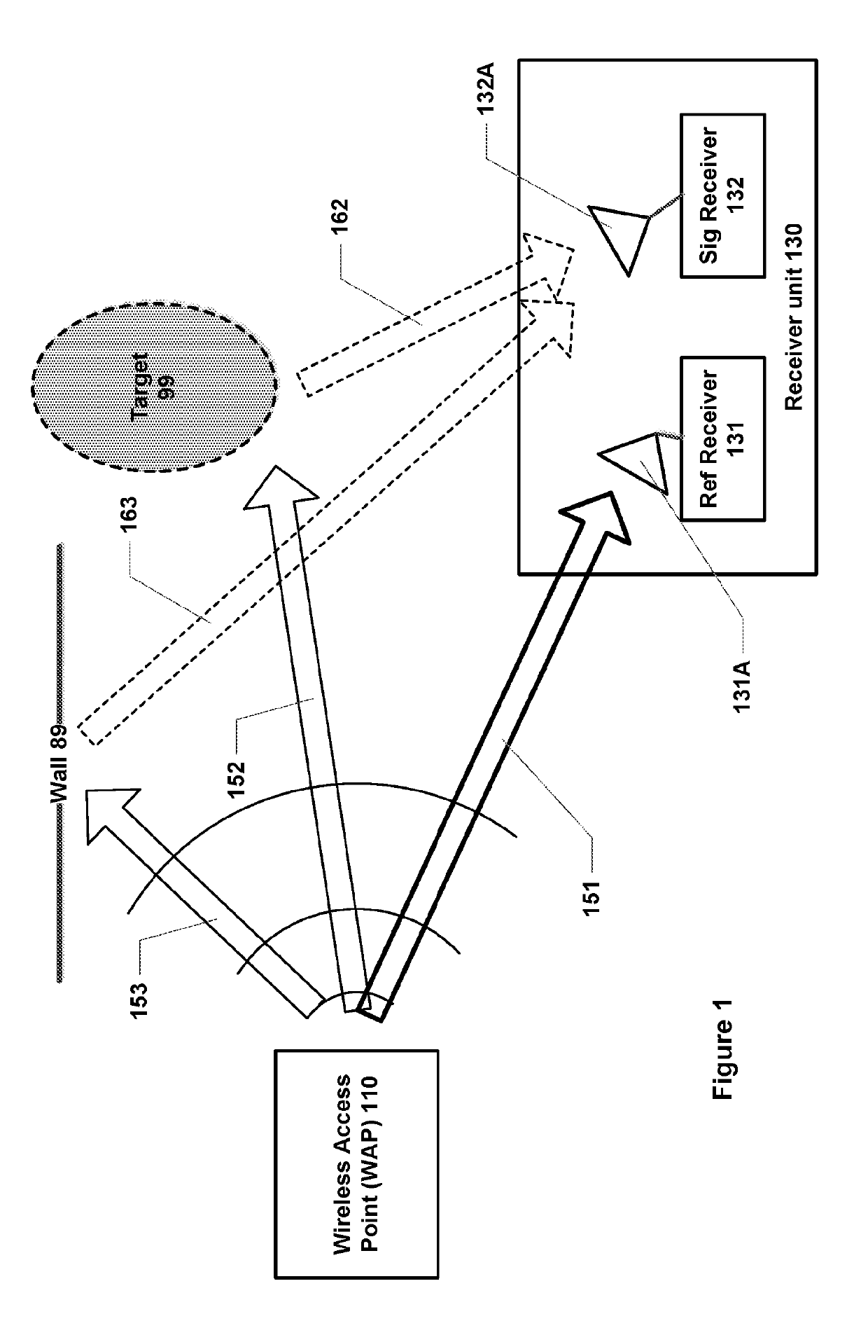
[0034]FIG. 1 is a general schematic illustration of passive sensing in accordance with some embodiments of the invention. It is assumed that a wireless access point (WAP) 110 exists at a given location. It will be appreciated that such wireless access points are very common, especially in urban settings, often to provide wireless local area network (WLAN) connectivity in accordance with the IEEE 802.11 standard (also referred to as “W-Fi”). As specified in the IEEE 802.11 standard, WAP 110 emits a beacon signal having a predetermined structure and content on a regular basis to allow devices within range to discover and connect to the wireless access point. WAP 110 also transmits and receives signals as part of two-way communications with any device that has connected to the wireless access point. Again, these communications have a predetermined structure (and, in part, content) according to the IEEE 802.11 standard. Note that the wireless access point 110 generally has low direction...


PUM


Abstract

A method and an apparatus are provided for performing passing sensing using wireless digital communications. The wireless digital communications are frame-based with a predefined frame structure. The method includes receiving a reference signal into to a reference channel, wherein the reference signal comprises a direct version of a radio frequency transmission as part of said wireless digital communications; receiving a surveillance signal into a surveillance channel; detecting and extracting portions of the reference signal corresponding to data transmissions based on said predefined frame structure; extracting portions of the surveillance signal corresponding to the extracted portions of the reference signal; performing a cross-correlation on the extracted portions of the reference signal and the surveillance signal to determine a range-Doppler surface; and providing a real-time display of said range-Doppler surface and / or of information derived therefrom.

Description

FIELD OF THE INVENTION[0001]The present application relates to a method and apparatus for performing passive sensing, for example using a W-Fi signal.BACKGROUND OF THE INVENTION[0002]Radio transmissions have been utilised for detecting objects for many years, since the first radar (radio detecting and ranging) systems. Radar is an example of an active sensing system, in which a radio signal is specifically transmitted towards a target or area of interest, and reflected signals are then analysed to detect any target within the area of interest. Active sensing systems such as radar are very widely used in many applications, such as air traffic control, meteorological measurements, and so on.[0003]Another form of radio sensing is passive sensing, in which there is no specific transmission of a radio signal towards a target. Rather, passive sensing relies on existing (background) radio signals that are generated and utilised for other purposes, and detects reflections from these other s...

Claims


Application Information

Patent Timeline
Patent Type & Authority Patents(United States)
IPC IPC(8): G01S7/41G01S13/00G01S13/02G01S13/58G01S7/42
CPCG01S13/003G01S7/418G01S13/58G01S13/0218G01S7/42
Inventor TAN, BOWOODBRIDGE, KARLCHETTY, KEVIN
Owner UCL BUSINESS PLC
Why Eureka
Try Eureka