Ultrasound probe and ultrasound image diagnostic apparatus

a technology of ultrasound image and ultrasound probe, which is applied in the field of ultrasonic probe and ultrasound image diagnostic apparatus, can solve the problems of deteriorating image quality more than that of pulse inversion method, easy penetration of high harmonic components in ultrasound signal, and inability to detect the reflected ultrasound signal from a deep part, etc., and achieves excellent distance resolution and reduce cancellation

Active Publication Date: 2019-05-28
KONICA MINOLTA INC
View PDF5 Cites 0 Cited by
  • Summary
  • Abstract
  • Description
  • Claims
  • Application Information

AI Technical Summary

Benefits of technology

[0015]An object of the present invention is to provide an ultrasound probe and an ultrasound image diagnosis apparatus which can obtain ultrasound images having an excellent distance resolution by reducing cancellation among a plurality of kinds of higher harmonics waves.

Problems solved by technology

In the meantime, there is a problem that the higher harmonic components contained in the ultrasound signal are easily influenced by attenuation when propagating through a test object because higher harmonic components generally have higher frequencies than that of the fundamental component, and accordingly penetration of the reflected ultrasound signal from a deep part is not good.
In addition, the filter method makes the extracted frequency band narrower, and accordingly the image quality deteriorates more than that of the pulse inversion method.
However, the technique described in Japanese Patent Application Laid-Open Publication No. 2002-301068 has the problem that when the plural kinds of higher harmonic components are used, cancellation among the plural higher harmonics waves occurs due to group delay characteristics of the ultrasound probe.
As a result, an intended distance resolution cannot be always obtained.

Method used


Image

  • Ultrasound probe and ultrasound image diagnostic apparatus
  • Ultrasound probe and ultrasound image diagnostic apparatus
  • Ultrasound probe and ultrasound image diagnostic apparatus

Examples


example 1

[0114]The above-described ultrasound probe A was used as the ultrasound probe 2.

[0115]The first pulse signal output from the transmission section 12 was the driving signal of the driving waveform A illustrated in FIG. 13A. FIG. 13B illustrates the frequency power spectrum obtained by the frequency analysis of the driving waveform A. FIG. 13C illustrates the group delay characteristics of the driving waveform A. In FIG. 13A, the horizontal axis indicates the time, and the vertical axis indicates the voltage. In FIG. 13B, the horizontal axis indicates the frequency, and the vertical axis indicates the signal intensity. In FIG. 13C, the horizontal axis indicates the frequency, and the vertical axis indicates the group delay amount.

[0116]The group delay characteristics was measured by measuring a voltage waveform at the time when a probe receptacle included in the ultrasound image diagnosis apparatus body was terminated with a resistance of 50Ω and driven, then performing the frequency ...

example 2

[0123]The above-described ultrasound probe B was used as the ultrasound probe 2.

[0124]The first pulse signal output from the transmission section 12 was the driving signal of the driving waveform A same as that of Example 1.

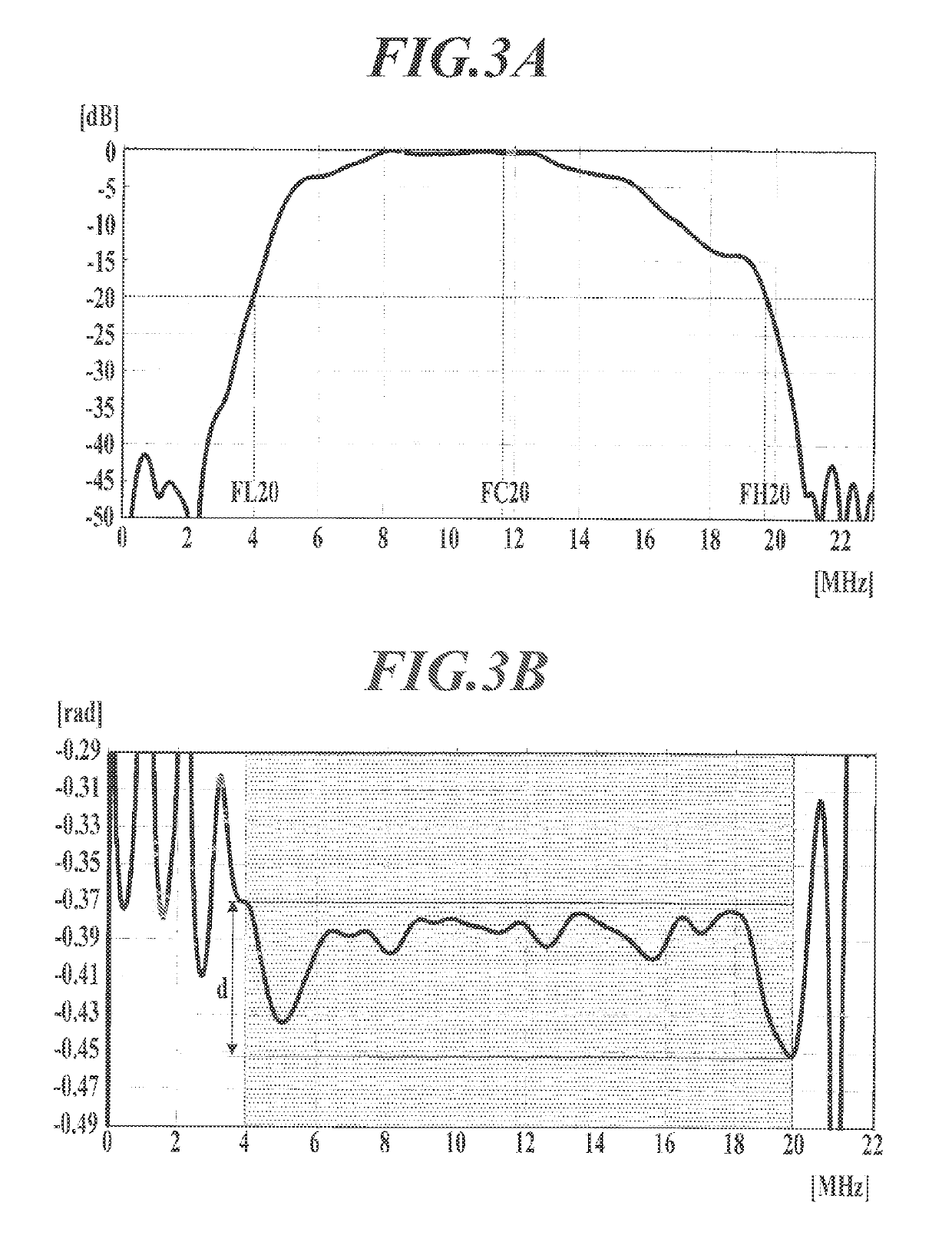
[0125]The driving waveform A had three intensity peaks in the transmission / reception frequency band (3.82 MHz to 19.86 MHz) at −20 dB of the ultrasound probe B, and one of the intensity peaks located on the low frequency side with respect to the center frequency (FC20: 11.84 MHz) in the transmission / reception frequency band at −20 dB of the ultrasound probe B, and other two intensity peaks located on the high frequency side with respect to the center frequency (FC20: 11.84 MHz) in the transmission / reception frequency band at −20 dB of the ultrasound probe B.

[0126]The pulse duration of the driving waveform A was 233 ns, which corresponded to 2.76 periods at the center frequency (FC20: 11.84 MHz) in the transmission / reception frequency band at −20 dB of the ultraso...

example 3

[0131]The above-described ultrasound probe A was used as the ultrasound probe 2.

[0132]The first pulse signal output from the transmission section 12 was the driving signal of the driving waveform A same as that of Example 1.

[0133]The second pulse signal was the driving signal of the driving waveform C illustrated in FIG. 15A. FIG. 15B illustrates the frequency power spectrum obtained by the frequency analysis of the driving waveform C. FIG. 15C illustrates the group delay characteristics of the driving waveform C. In FIG. 15A, the horizontal axis indicates the time, and the vertical axis indicates the voltage. In FIG. 15B, the horizontal axis indicates the frequency, and the vertical axis indicates the signal intensity. In FIG. 15C, the horizontal axis indicates the frequency, and the vertical axis indicates the group delay amount.

[0134]The driving waveform C had two intensity peaks in the transmission / reception frequency band (3.99 MHz to 19.72 MHz) at −20 dB of the ultrasound prob...


PUM


Abstract

An ultrasound probe includes: an ultrasound input / output unit to output a transmission ultrasound to a test object by a pulse signal; and a signal input / output unit to output a reception signal when the ultrasound input / output unit receives a reflected ultrasound from the test object, wherein the ultrasound probe is set so that a difference between maximum and minimum values of a group delay in a transmission / reception frequency band at −20 dB of the ultrasonic probe is equal to or less than 0.15 radian, the group delay being obtained from a phase difference for each frequency between the input pulse signal and the reception signal obtained from the reflected ultrasound of the transmission ultrasound output by the pulse signal, or so that a standard deviation of the group delay in the transmission / reception frequency band at −20 dB of the ultrasonic probe is equal to or less than 0.025.

Description

CROSS REFERENCE TO RELATED APPLICATION[0001]This Application claims the priority of Japanese Patent Application No. 2014-082675 filed on Apr. 14, 2014, which is incorporated by reference herein.BACKGROUND OF THE INVENTION[0002]Field of the Invention[0003]The present invention relates to an ultrasound probe and an ultrasound image diagnostic apparatus.[0004]Description of Related Art[0005]According to ultrasound diagnostics, a realtime display of heartbeat and / or motion of a fetus can be executed by a simple operation of applying an ultrasound probe to a body surface. Additionally, the ultrasound diagnostics are excellent in safety, and enable repeated examinations.[0006]With regard to such technique to display ultrasound images, it has been known that a high contrast image can be obtained by imaging higher harmonic components (e.g. frequencies 2f0, 3f0, etc.) with respect to a fundamental component (frequency f0) of a transmission signal. This imaging method is referred to as Tissue...

Claims


Application Information

Patent Timeline
Patent Type & Authority Patents(United States)
IPC IPC(8): A61B8/08A61B8/14G01S15/89A61B8/00G01S7/52
CPCA61B8/5269A61B8/08A61B8/4444A61B8/4483A61B8/5207G01S7/5202G01S7/52038G01S7/52047G01S15/895A61B8/54A61B8/48A61B8/0866
Inventor TANIGUCHI, TETSUYA
Owner KONICA MINOLTA INC
Why Eureka
Try Eureka