
Measuring apparatus with remote control

a technology of measuring apparatus and remote control, which is applied in the direction of measurement devices, structural/machine measurement, and material strength using single impulsive force, etc., can solve the problems of affecting the sensitivity of the receiver and therefore the quality of the connection, affecting the quality of communication, and high total energy requirements, so as to reduce the power consumption of the measuring apparatus and increase the service life. , the effect of increasing the service li

Active Publication Date: 2019-05-28
ROSENBERGER HOCHFREQUENZTECHNIK GMBH & CO KG
View PDF21 Cites 0 Cited by
  • Summary
  • Abstract
  • Description
  • Claims
  • Application Information

AI Technical Summary

Benefits of technology

[0013]According to the present invention, components of the measuring apparatus which have a high power consumption can be switched off in a permanent condition and can be switched on by means of remote control only when the motion sensor in the test hammer sends a control signal to the measuring apparatus to switch on these components. The power consumption of the measuring apparatus can thereby be reduced and the service life increased. Due to the reduced power consumption, smaller batteries and smaller can be used, as a result of which the weight of the apparatus can be reduced. Furthermore, the operation of the measuring apparatus is simplified. The result of the measurement is preferably displayed directly on the test hammer.

Problems solved by technology

Due to the high generated power in the BTS on the one hand and the necessary sensitivity of the receivers of the BTS and the UE on the other hand, interference in the transmission path can substantially influence the sensitivity of the receivers and therefore the quality of the connection.
A part of this interference can be in the receive band of the BTS and thus adversely affect the quality of the communication.
For example, corrosion in plug-in connectors, oxide layers on contacts and metal-to-metal transitions, contamination in materials and inadequately attached plug-in connections can cause PIM.
The high power consumption, particularly of the power amplifiers, and the applied measuring method in which the power amplifiers are continuously in operation while the individual contact points are successively subjected to tapping result in a high total energy requirement.
However, only relatively heavy measuring apparatus have hitherto been available in which, on the one hand, due to the high total energy requirement, large batteries or accumulators are used, but, on the other hand, also due to the high power consumption and the resulting power dissipation, large and heavy heat sinks are fitted to remove the waste heat.

Method used


Image

  • Measuring apparatus with remote control
  • Measuring apparatus with remote control
  • Measuring apparatus with remote control

Examples


Embodiment Construction

[0021]An embodiment of the present invention is described in detail below with reference to the attached figures.

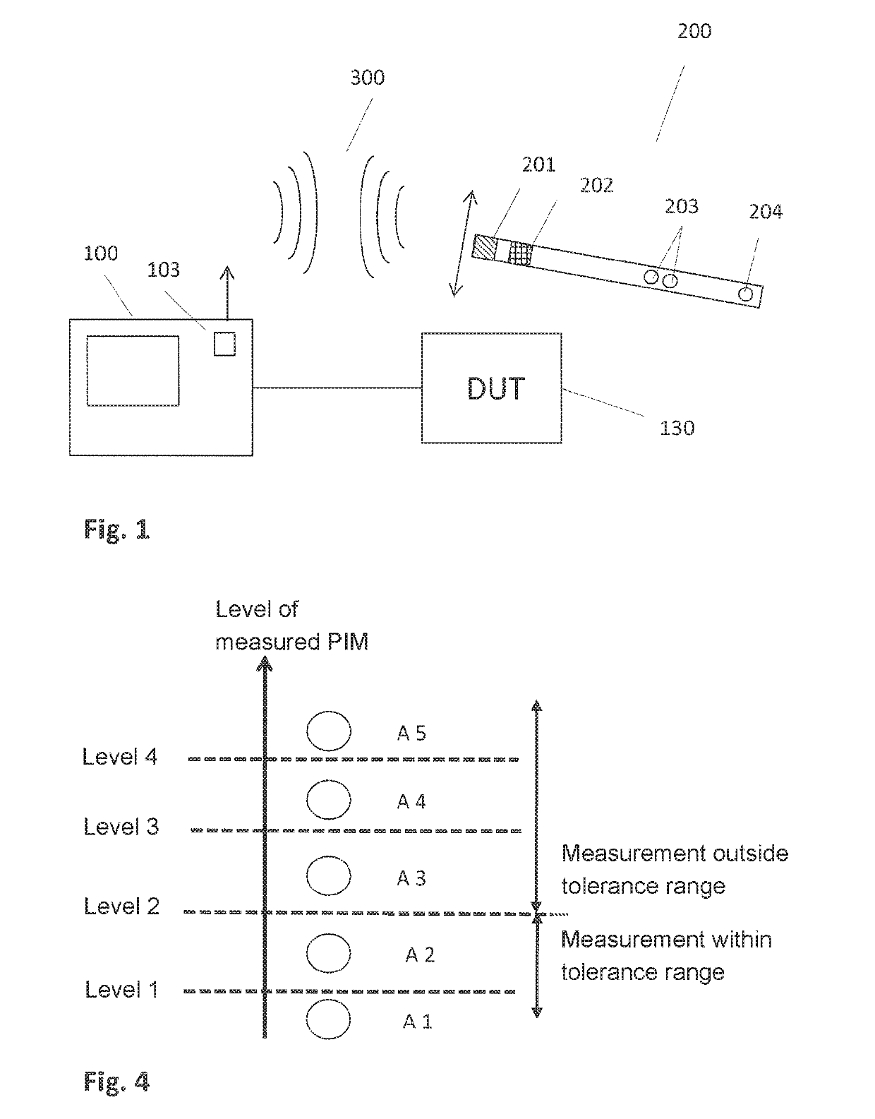
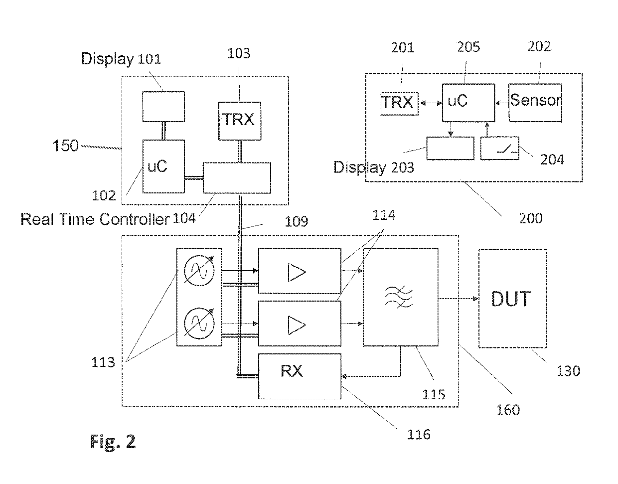
[0022]FIG. 1 is a schematic representation showing a test system according to one embodiment of the present invention. A measuring apparatus 100 which is designed as a PIM analyzer is connected to the device under test (DUT) 130. The DUT may, for example, be a transmission path between a BTS 10 and an antenna 13, as shown in FIG. 5 and described in the introduction to the description. In this case, the measuring apparatus 100 is connected, for example, via the high-frequency connector 17 to the high-frequency cable 14.

[0023]The tool with which individual points of the transmission path are tapped is designed according to the invention as a test hammer 200. The test hammer 200 contains a transmission module 201, a motion sensor 202, one or more display elements 203 (two display elements are shown in FIG. 2) and at least one button 204. The test hammer 200 and the measuring...


PUM

PropertyMeasurementUnit
timeaaaaaaaaaa
angleaaaaaaaaaa
accelerationaaaaaaaaaa

Abstract

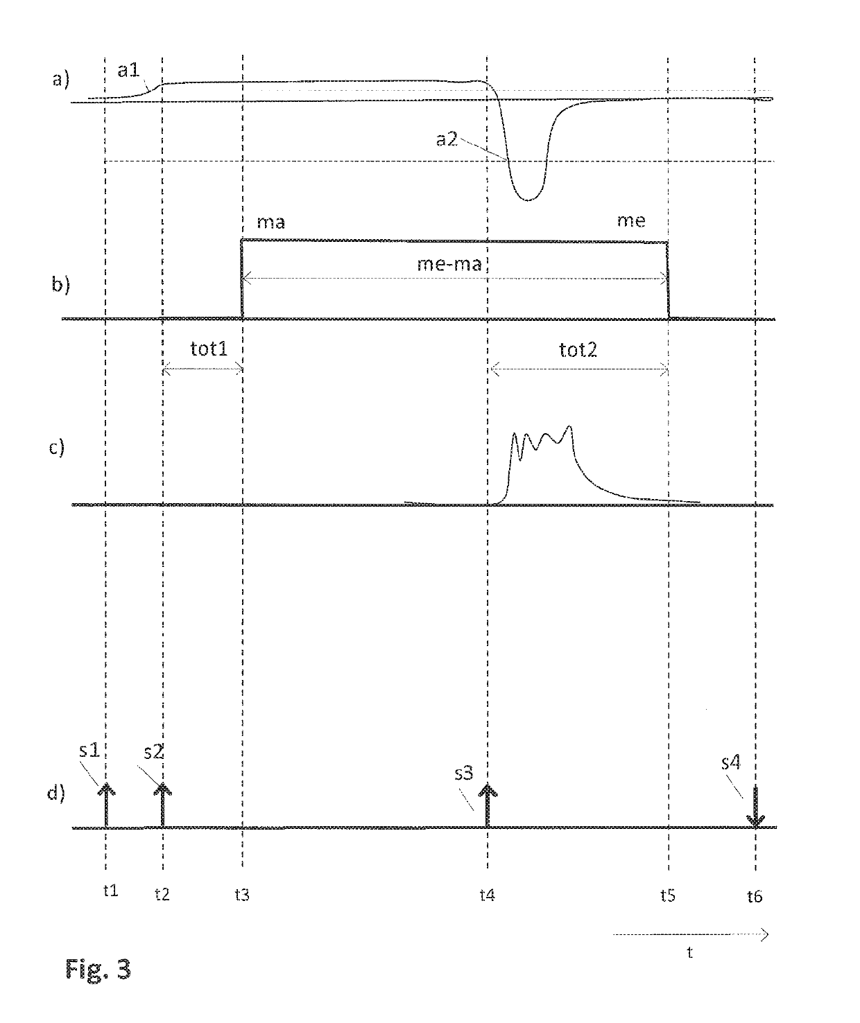
A test system includes a measuring apparatus for measuring a property of a device under test and a test hammer for carrying out a strike on a section of the device. The test hammer includes a motion sensor and a transmission module for transmitting a signal if the motion sensor detects the start of the strike, and / or for transmitting a signal if an impact is detected. Further, a test signal generating unit generates a test signal, a test signal output unit outputs the test signal to the device under test, a measuring signal receiving unit receives a measuring signal produced in response to the output of the test signal, an analyzing unit determines a quantity of a component of the measuring signal, a transmission module receives a control signal from an external source, and a real-time controller switches from the energy-saving mode.

Description

BACKGROUND OF THE INVENTION1. Field of the Invention[0001]The present invention relates to measuring systems for high-frequency communication systems, specifically for measuring apparatus for measuring passive intermodulation.2. Discussion of the Related Art[0002]The quality of a connection between a permanently installed transceiver device (BTS, Base Transceiver Station) and a terminal device (UE, User Equipment) plays an essential role in today's mobile networks. Due to the high generated power in the BTS on the one hand and the necessary sensitivity of the receivers of the BTS and the UE on the other hand, interference in the transmission path can substantially influence the sensitivity of the receivers and therefore the quality of the connection.[0003]Intermodulation is a determining effect causing interference in the transmission path. Two transmit signals, for example, with two different carrier frequencies which are generated at high power in a BTS generate interference due t...

Claims


Application Information

Patent Timeline
Patent Type & Authority Patents(United States)
IPC IPC(8): G01N3/30G01M7/08
CPCG01M7/08G01N3/30
Inventor SCHWAB, MARTIN
Owner ROSENBERGER HOCHFREQUENZTECHNIK GMBH & CO KG
Learn More