Supercharger cooling means

a supercharger and cooling means technology, applied in the direction of engine cooling apparatus, combustion engines, machines/engines, etc., can solve the problems of limited supercharger boost pressure, no cooling benefits, no cooling benefits, etc., and achieve the effect of lower operating temperature and higher operating pressure capability

Inactive Publication Date: 2019-06-11
MENDLER III EDWARD CHARLES
View PDF8 Cites 2 Cited by
  • Summary
  • Abstract
  • Description
  • Claims
  • Application Information

AI Technical Summary

Benefits of technology

[0009]According to the present invention, a rotary blower or supercharger includes a recirculation loop for readmitting pressurized outlet gas back into the rotor chambers, and cooling means for cooling the pressurized outlet gas before it is readmitted into the rotor chambers, thereby providing a supercharger having a lower operating temperature and a higher operating pressure capability.
[0013]Another objective of the present invention is to minimize the marginal cost increase for the supercharger and cooling means of the present invention, and to provide close-coupled cooling of the recirculation gas. An advantage of close-coupled cooling or intercooling is that boost pressure can be provided with minimal lag time. A short lag time is important for downsized internal combustion engines providing a similar responsiveness to that of larger naturally aspirated engines. According to an embodiment of the present invention having a close-coupled intercooler, the recirculation port is located in the intercoolers outlet plenum. According to an embodiment of the present invention, the intercooler outlet plenum and rotor cylindrical chamber share a cast wall, and the recirculation port generally comprises a low-cost hole through the shared wall. The embodiment of the present invention provides significant cooling benefits at no or almost no increase in supercharger cost relative to current production supercharger having close-coupled intercoolers but not the cooling technology of the present invention. Additional embodiments of the present invention for achieving supercharger cooling and a low marginal cost are described in the Detailed Description of the Preferred Embodiments.
[0014]The primary objective of the present invention is to provide a cooler running supercharger so that higher outlet pressures can be generated without over heating the supercharger. A second objective is to increase supercharger efficiency through improved cooling, tighter operating clearances and lessen leakage. Tighter operating clearances can be attained by cooling the supercharger and reducing thermal expansion of the rotors and supercharger housing assembly. A third objective is to provide a high-flow capacity supercharger, and in more detail to provide cooling means according to the present invention without substantively reducing the flow and output capacity of the supercharger. A fourth objective is to provide close-coupled intercooling of the supercharger to provide a fast response and a low marginal cost increase for the present invention.

Problems solved by technology

The boost pressure that a supercharger can deliver is currently limited by overheating of the supercharger.
The backflow slots reduce noise but have no reported cooling benefits.
The blow hole reportedly reduces noise but does not provide cooling benefits.
A problem with prior art superchargers is that their working pressure or pressure ratio capability is limited by overheating.
The working pressure can be increased by using large clearances between the rotors and housings to accommodate thermal expansion, but the large clearances result in increased leakage and lower supercharger efficiency.

Method used


Image

  • Supercharger cooling means
  • Supercharger cooling means
  • Supercharger cooling means

Examples


Embodiment Construction

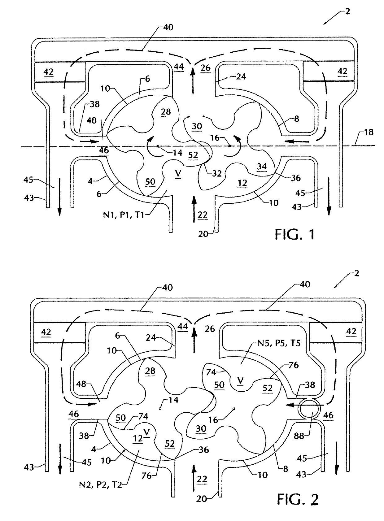
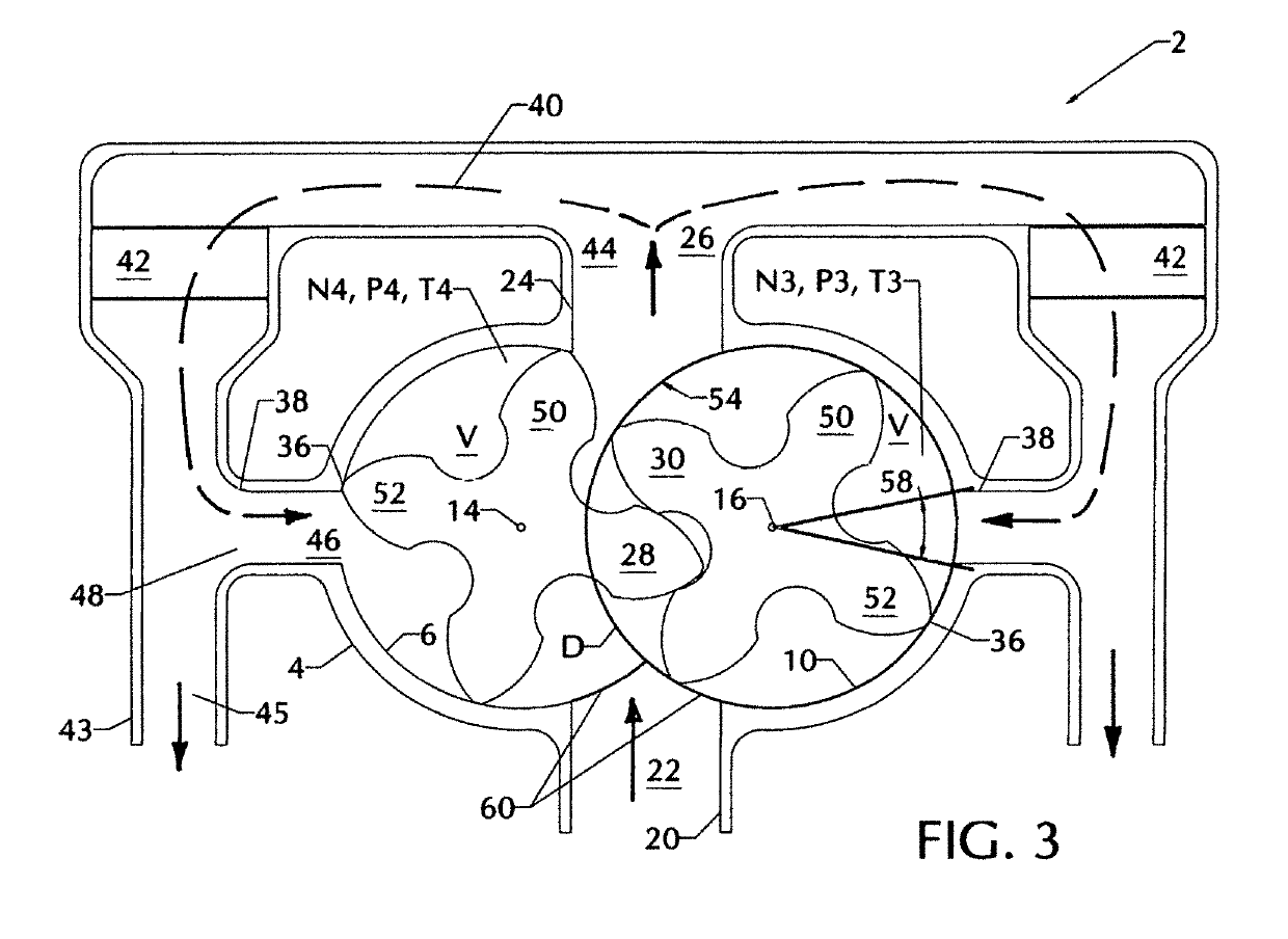
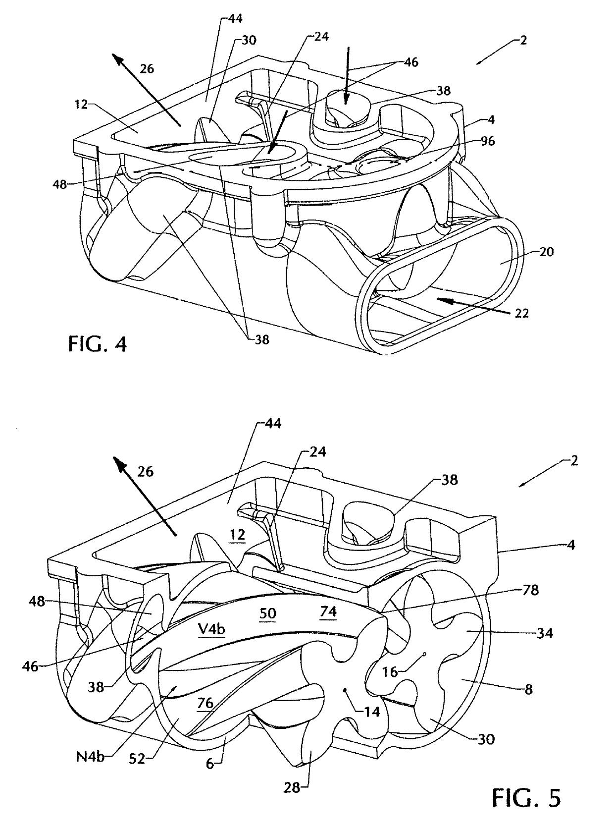
[0027]FIGS. 1, 2, 3, 4, 5 and 11 are intended to illustrate a rotary blower or supercharger 2 with cooling means 42 according to the present invention. FIGS. 1, 2 and 3 are similar but show the supercharger lobed rotors 28 and 30 at different rotational positions. FIG. 4 shows a perspective view of a portion of the supercharger according to the present invention. FIG. 5 is similar to FIG. 4, but shows a partial cutaway view to better show the cool air recirculation port 38 according to the present invention.

[0028]Rotary blower or supercharger 2 includes a housing assembly 4 defining first 6 and second 8 transversely overlapping cylindrical chambers having internal cylindrical wall surfaces 10 and end wall surfaces 12. Chamber 6 has a first central axis 14, and chamber 8 has a second central axis 16. First central axis 14 and second central axis 16 are spaced apart and parallel, and lie in a common plane 18. The housing 4 defines an inlet port 20 for the inflow of an inlet gas 22, an...


PUM


Abstract

According to the present invention, a rotary blower or supercharger includes a recirculation loop for readmitting pressurized outlet gas back into the rotor chambers, and cooling means for cooling the pressurized outlet gas before it is readmitted into the rotor chambers, thereby providing a supercharger having a lower operating temperature and a higher operating pressure capability. In the preferred embodiment of the present invention, a supercharger includes a housing assembly defining first and second transversely overlapping cylindrical chambers. The housing defines an inlet port for the inflow of an inlet gas, and an outlet port for the outflow of the outlet gas. The supercharger further has first and second meshed, lobed rotors respectively disposed in the chambers for counter rotation about axes substantially coincident with the chamber axes. According to the present invention, the housing further includes a recirculation port and a recirculation flow path for recirculation of a portion of outlet gas flowing out of the outlet port back into cylindrical chamber. The recirculation flow path further including cooling means for cooling of at least a portion of the outlet gas, thereby providing a cooler operating supercharger.

Description

[0001]This application relates to Provisional Application No. 61 / 996,151 having a filing date of Apr. 30, 2014. The present invention was made during performance of work under United States Department of Energy contract number DE-EE0005981.BACKGROUND OF THE INVENTION[0002]This invention relates to cooling means for Roots-type superchargers or rotary blowers. More specifically, the present invention relates to means for cooling the supercharger to enable the supercharger to produce higher boost pressures. The present invention may be employed as a supercharger for internal combustion engines and for other purposes such as an air or gas compressor.[0003]A major strategy being employed for improving automobile fuel economy is engine downsizing, or reducing the displacement and number of cylinders of the engine. Supercharging enables a small displacement engines to achieve the same power output as a larger displacement naturally aspirated engine. The degree of engine downsizing that can...

Claims


Application Information

Patent Timeline
Patent Type & Authority Patents(United States)
IPC IPC(8): F02B29/04F02B33/38F02B39/16
CPCF02B33/38F02B29/0475F02B39/16Y02T10/146F01P2060/02F02B2039/164Y02T10/12
Inventor MENDLER, III, EDWARD CHARLES
Owner MENDLER III EDWARD CHARLES
Why Eureka
Try Eureka