Photovoltaic module with a controllable infrared protection layer

a photovoltaic module and infrared protection technology, applied in the field of photovoltaic modules, can solve the problems of significant carriers, significant efficiency degradation, and high cost, and achieve the effect of maximizing the efficiency of the photovoltaic module, eliminating the need for a complicated control system, and good ultraviolet protection

Active Publication Date: 2019-06-11
INT BUSINESS MASCH CORP
View PDF15 Cites 1 Cited by
  • Summary
  • Abstract
  • Description
  • Claims
  • Application Information

AI Technical Summary

Benefits of technology

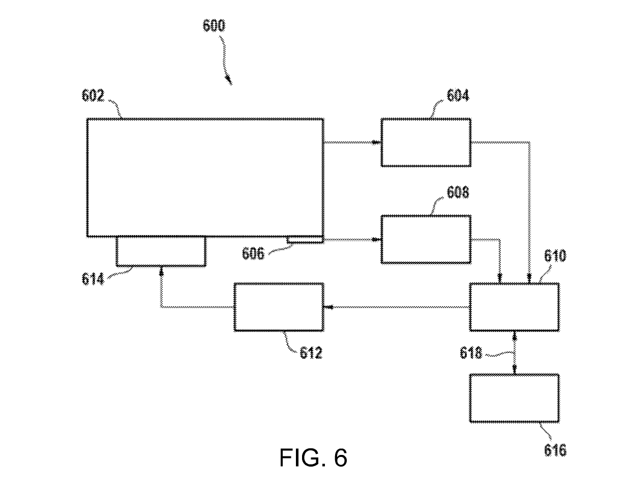
[0008]This approach has the advantage that the photovoltaic device operates at low ambient temperature with maximum efficiency. Also a generic maintenance support feature may be included to run photovoltaic modules more efficiently and reliably.
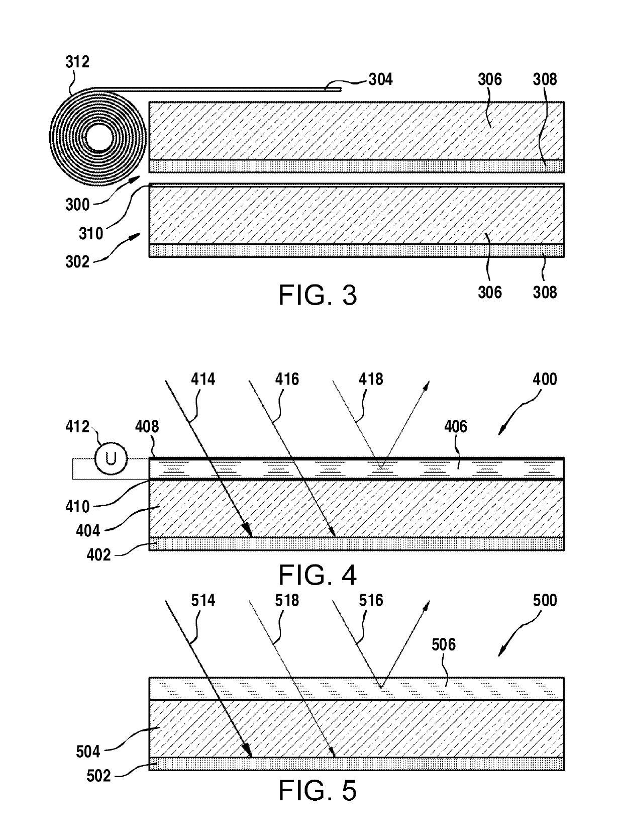
[0038]In another embodiment the photovoltaic module system further comprises an infrared absorber. The infrared absorber is adapted for moving between a stored position and a deployed position. The infrared absorber is adapted for heating the photovoltaic module using absorbed infrared radiation when in the deployed position. The control system is adapted for signaling the infrared absorber to move between the stored position and the deployed position based upon the maintenance schedule. This embodiment is particularly advantageous, because with use the efficiency of photovoltaic modules may decrease. This is particularly true for photovoltaic modules which are manufactured using thin film technology. The efficiency of thin film photovoltaic modules can be restored by heating them or elevating its temperature for a period of time. By placing the infrared absorber in the deployed position, sunlight can be used to heat the photovoltaic module of the photovoltaic module system. The maintenance schedule can therefore be used to perform the heating of the module to increase the efficiency.

Problems solved by technology

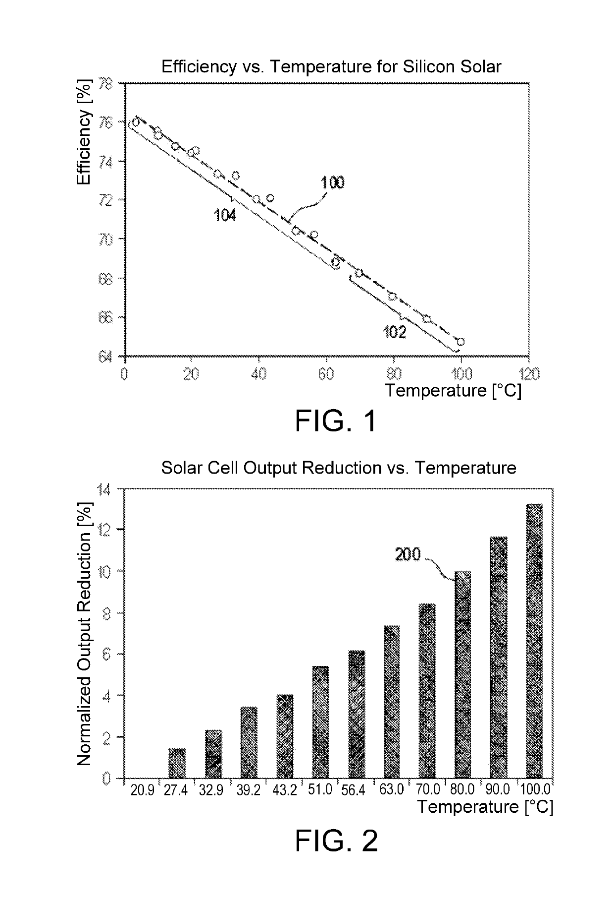
The infrared and ultraviolet parts of sunlight may cause heating for solar energy device operation.
The elevated temperature generated by infrared and ultraviolet exposure causes efficiency degradation which can be quite substantial.
In addition, infrared and ultraviolet radiation does not generate significant carriers for generation of electricity using the photovoltaic effect.

Method used


Image

  • Photovoltaic module with a controllable infrared protection layer
  • Photovoltaic module with a controllable infrared protection layer
  • Photovoltaic module with a controllable infrared protection layer

Examples


Embodiment Construction

[0059]As will be appreciated by one skilled in the art, aspects of the present invention may be embodied as an apparatus, a system, method or computer program product. Accordingly, aspects of the present invention may take the form of an entirely hardware embodiment or an embodiment combining software (including firmware, resident software, micro-code, etc.) and hardware aspects that may all generally be referred to herein as a “circuit,”“module” or “system.” Furthermore, aspects of the present invention may take the form of a computer program product embodied in one or more computer readable medium(s) having computer readable program code embodied thereon.

[0060]Many of the functional units described in this specification have been labeled as modules, in order to more particularly emphasize their implementation independence. For example, a module may be implemented as a hardware circuit comprising custom VLSI circuits or gate arrays, off-the-shelf semiconductors such as logic chips,...


PUM


Abstract

An apparatus, system, and method are disclosed for a photovoltaic module, the photovoltaic module comprising a plurality of photovoltaic cells, a controllable infrared protection layer, and a protection switching means. The controllable infrared protection layer is for reducing the infrared radiation absorbed by the photovoltaic module, where the controllable infrared protection layer has a first state and a second state. When the infrared protection layer is in the first state the transmission of infrared radiation to the photovoltaic cells is higher than when the infrared protection layer is in the second state. The protection switching means is for switching the controllable infrared protection layer between the first state and the second state.

Description

CROSS-REFERENCE TO RELATED APPLICATIONS[0001]This application claims priority to European Patent Application Number EP09174791 entitled “PHOTOVOLTAIC MODULE WITH A CONTROLLABLE INFRARED PROTECTION LAYER” and filed on Nov. 2, 2009 for Lawrence A. Clevenger, et al. which is incorporated herein by reference.FIELD[0002]The subject matter disclosed herein relates to photovoltaic modules, in particular it relates to photovoltaic modules with a controllable infrared protection layer.BACKGROUND[0003]Photovoltaic modules use a plurality of photovoltaic cells to produce electricity using the photovoltaic effect. Photovoltaic cells may be manufactured in a variety of ways, however the use of semiconductor wafers to manufacture photovoltaic cells or the use of thin semiconductor films deposited upon a substrate are common methods of manufacturing photovoltaic modules. The use of silicon for the semiconductor is also very common.[0004]A difficulty that many types of photovoltaic modules have is ...

Claims


Application Information

Patent Timeline
Patent Type & Authority Patents(United States)
IPC IPC(8): H01L31/00H01L31/054H01L31/049H01L31/048G02B26/00
CPCH01L31/0549G02B26/007H01L31/049H01L31/0488H01L31/048Y02E10/52
Inventor CLEVENGER, LAWRENCE A.DALTON, TIMOTHY J.DARNON, MAXIMEKRAUSE, RAINERPFEIFFER, GERDPRETTYMAN, KEVINRADENS, CARL J.SAPP, BRIAN C.
Owner INT BUSINESS MASCH CORP
Why Eureka
Try Eureka