
Borehole inspection device

a technology for inspection devices and boreholes, which is applied in the direction of optical apparatus testing, television systems, instruments, etc., can solve the problems of unusable workpieces containing boreholes, and achieve the effect of expanding relatively easily

Active Publication Date: 2019-06-25
JENOPTIK IND METROLOGY GERMANY
View PDF40 Cites 9 Cited by
  • Summary
  • Abstract
  • Description
  • Claims
  • Application Information

AI Technical Summary

Benefits of technology

[0010]An object of the invention is to provide a device for inspecting a borehole in a workpiece, which is improved with regard to the detection of surface defects on the inner wall of the borehole.
[0021]One particular advantage of the device according to the invention is that the surface depth information is obtained anyway from the images recorded during the axial movement of the measuring head, so that obtaining the surface depth information does not require additional time. This is extremely advantageous with regard to short cycle times during the inspection of boreholes. Another advantage of the device according to the invention is that the evaluation apparatus, which is present anyway in devices of the type in question, may be expanded relatively easily with regard to 3D reconstruction.
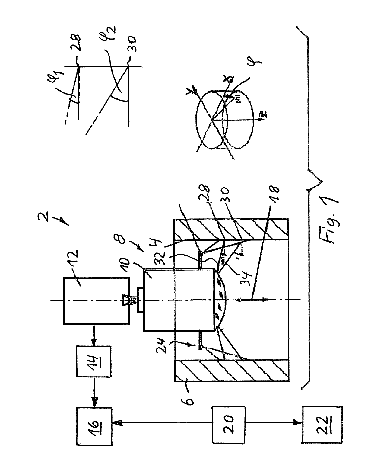
[0024]One advantageous further embodiment of the embodiment mentioned above provides that the control apparatus transmits position data, which represent the particular axial position of the measuring head, to the evaluation apparatus in order to associate the particular axial position of the measuring head with an image recorded in this position. In this embodiment, associating an axial position of the measuring head, and thus with regard to a surface location, with the resulting viewing angle of the imaging optics for the image recorded in this axial position is possible in a particularly easy manner.

Problems solved by technology

If the anomaly is a depression, a surface defect is possibly present which may make the workpiece which contains the borehole unusable.

Method used


Image

  • Borehole inspection device
  • Borehole inspection device

Examples


Embodiment Construction

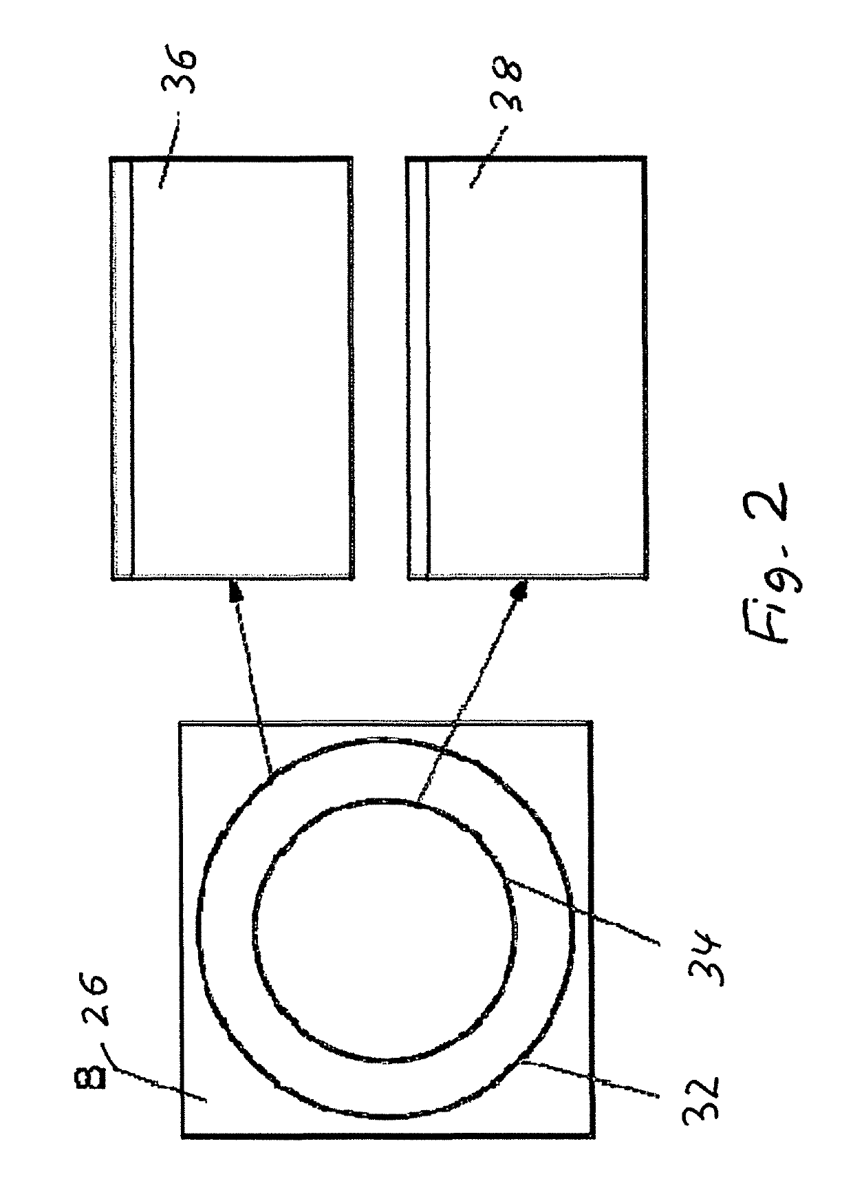
[0037]FIG. 1 illustrates one embodiment of a borehole inspection device 2 according to the invention for inspecting a borehole in a workpiece 6, having a measuring head 8 which is designed as an endoscope and is insertable into the borehole 4 to be inspected and movable relative to the borehole 4 in different axial positions, and which has an imaging optics 10 with a panoramic view for imaging the inner surface of the borehole 4. The imaging optics is in image transmission connection with a digital image recorder 12.

[0038]The device 2 also has a memory 14 for storing the images recorded in different axial positions of the measuring head 8, the memory 14 being in image transmission connection with the digital image recorder 12.

[0039]An evaluation apparatus 16 is provided for evaluating the images stored in the memory 14.

[0040]In order to move the measuring head 8 relative to the borehole 4 in the axial direction thereof, and thus to axially position the measuring head 8 (double arrow...


PUM

PropertyMeasurementUnit
angleaaaaaaaaaa
surface depthaaaaaaaaaa
image processingaaaaaaaaaa

Abstract

Borehole inspection device for inspecting a borehole in a workpiece has a measuring head which includes an endoscope and is insertable into the borehole to be inspected and movable relative to the borehole in different axial positions. Borehole inspection device has an imaging optics with a panoramic view for imaging the inner surface of the borehole, and the imaging optics is in image transmission connection with a digital image recorder. Device has a memory for storing the images recorded in different axial positions of the measuring head, and an evaluation apparatus for evaluating the images stored in the memory. In order to obtain surface depth information about the inner surface of the borehole, the evaluation apparatus is configured for evaluating images recorded at different viewing angles of the imaging optics with regard to the particular surface location, using a 3D reconstruction method.

Description

CROSS-REFERENCE TO RELATED APPLICATIONS[0001]This application claims the priority of German Application No. 10 2015 010 225.7, filed Aug. 12, 2015, which is incorporated herein by reference.FIELD OF THE INVENTION[0002]The invention relates to a borehole inspection device for inspecting a borehole in a workpiece.BACKGROUND OF THE INVENTION[0003]Borehole inspection devices of this type, which are also called internal test sensors and also referred to below as devices for short, are used, for example, for borehole inspection in crankcases for internal combustion engines. They are used to image the radial inner surface of the borehole, and, based on the imaging using image processing and pattern recognition methods, to check whether the radial inner surface meets the predetermined requirements for surface quality.[0004]Such devices are known from NO 2009 / 003692, DE 4416493 A1, DE 4320845 C1, and DE 3232904 C2, for example.[0005]An imaging system for three-dimensional imaging of the inte...

Claims


Application Information

Patent Timeline
Patent Type & Authority Patents(United States)
IPC IPC(8): G02B23/24H04N5/225H04N5/232
CPCG02B23/2415G02B23/2446G02B23/2461H04N5/2256H04N5/23238G02B23/2484H04N2005/2255G01B11/22G01N21/954E06B7/14E06B7/2307E06B7/2312G01B11/12G01B11/24G01M11/081G01N11/12G02B13/06G02B23/243G03B35/06G03B37/005G03B2215/0503G01M13/00H04N23/555H04N23/56H04N23/698
Inventor RUDOLF, MICHAEL
Owner JENOPTIK IND METROLOGY GERMANY
Learn More