Eureka AIR delivers breakthrough ideas for toughest innovation challenges, trusted by R&D personnel around the world.

Driving circuit of active-matrix organic light-emitting diode with hybrid transistors

a technology of organic light-emitting diodes and driving circuits, applied in the field of display panels, can solve the problems of increased current consumption, poor brightness, uniform brightness, etc., and achieve the effects of large driving capability, reduced threshold voltage variation, and large curren

Active Publication Date: 2019-06-25
INNOLUX CORP
View PDF10 Cites 0 Cited by
  • Summary
  • Abstract
  • Description
  • Claims
  • Application Information

AI Technical Summary

Benefits of technology

[0007]The object of the present disclosure is to provide a driving circuit of active-matrix organic light-emitting diode with hybrid transistors, in which the transistor in a current drive unit of the driving circuit is a low temperature poly-silicon (LTPS) transistor. The LTPS transistor can provide large current in its turn-on state with a large driving capability for driving an organic light-emitting diode (OLED). At the same time, partial transistors in a reset compensation and light emitting control circuit of the driving circuit are replaced by oxide semiconductor transistors for providing a low leakage current to reduce the variation of the threshold voltage of the transistor in the current drive unit. Therefore, the transistor in the current drive unit can provide a stable driving current to the OLED to overcome the mura or poor brightness uniformity problem.
[0008]Another object of the present disclosure is to provide a transistor sharing architecture between two driving circuit for dramatically reducing the number of transistors.

Problems solved by technology

Accordingly, when driving voltages of the same value are inputted to two P-type driving transistors of the same size, they cannot output currents of the same value, resulting in a brightness uniformity (mura) or poor brightness problem.
In performing the voltage compensation, there are a plurality of transistors required for the driving circuit, which results in increased current consumption.

Method used


Image

  • Driving circuit of active-matrix organic light-emitting diode with hybrid transistors
  • Driving circuit of active-matrix organic light-emitting diode with hybrid transistors
  • Driving circuit of active-matrix organic light-emitting diode with hybrid transistors

Examples


Embodiment Construction

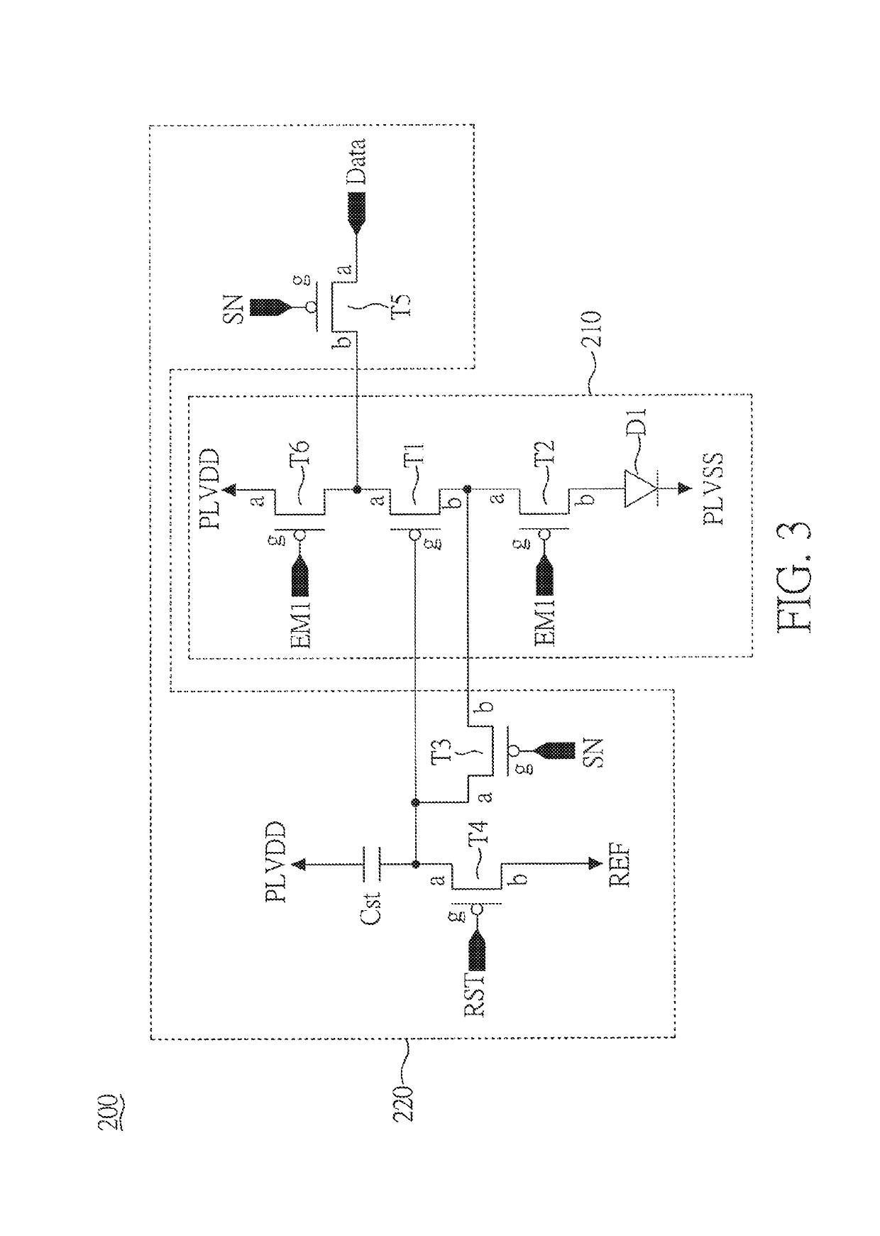
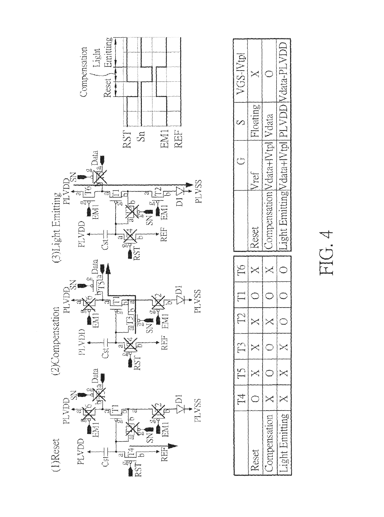
[0029]FIG. 2 is a block diagram of a driving circuit 200 of active-matrix organic light-emitting diode with hybrid transistors according to the present disclosure. As shown in FIG. 2, the driving circuit 200 includes a current drive unit 210 and a reset compensation and light emitting control circuit 220. The driving circuit 200 is provided to drive an active-matrix organic light-emitting diode (AM-OLED) D1. The current drive unit 210 includes a first transistor (T1) and a second transistor (T2) which are connected in series, wherein the first transistor (T1) and the second transistor (T2) comprises a silicon semiconductor layer, respectively. The silicon semiconductor layer is a low temperature poly-silicon (LTPS) layer. That is, the first transistor (T1) and the second transistor (T2) are LTPS transistors. The reset compensation and light emitting control circuit 220 is coupled to the current drive unit 210. The reset compensation and light emitting control circuit 220 includes a ...


PUM


Abstract

A driving circuit includes a current drive unit and a reset compensation and light emitting control circuit. The current drive unit includes a first transistor and a second transistor. The first transistor and the second transistor are connected in series, wherein the first transistor and the second transistor include a silicon semiconductor layer. The reset compensation and light emitting control circuit is coupled to the current drive unit. The reset compensation and light emitting control circuit includes a third transistor connected to a control terminal of the first transistor, wherein the third transistor is an oxide semiconductor transistor.

Description

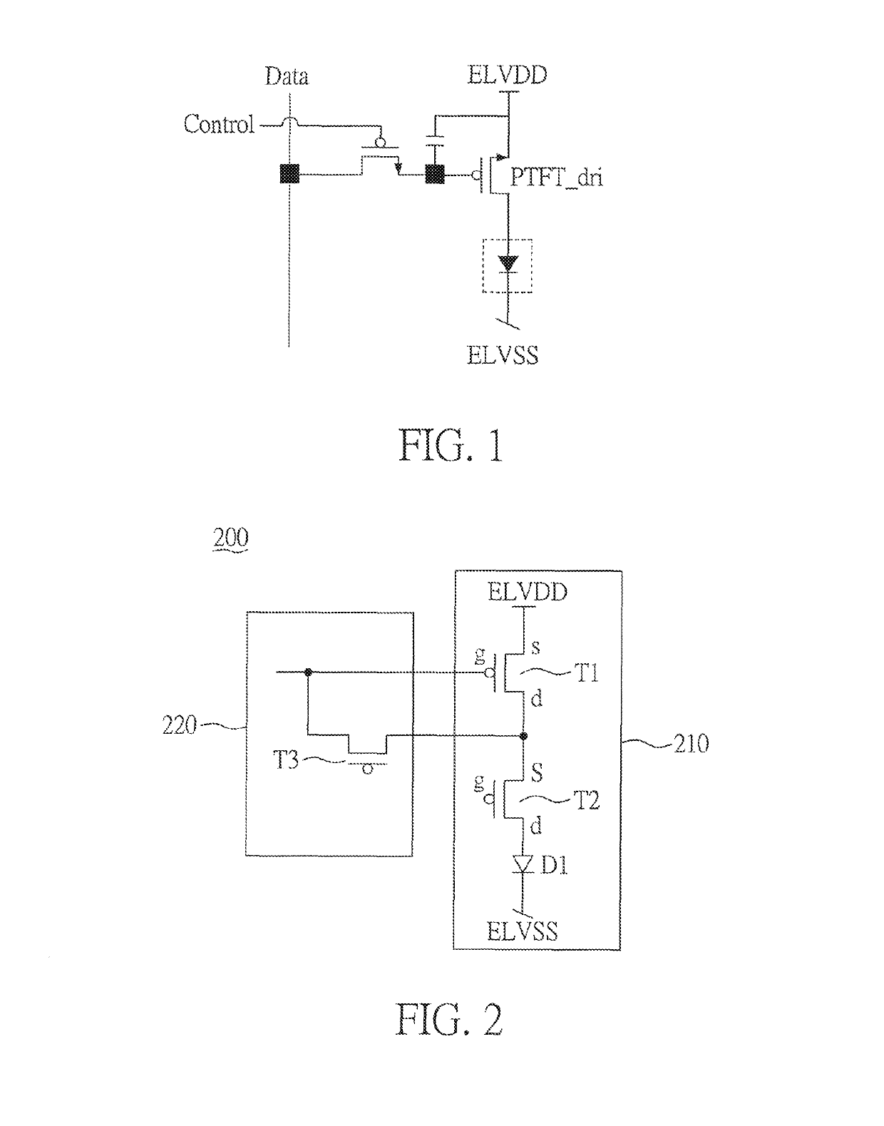
BACKGROUND[0001]1. Field of the Disclosure[0002]The present disclosure relates to the technical field of display panels and, more particularly, to a driving circuit of active-matrix organic light-emitting diode with hybrid transistors.[0003]2. Description of Related Art[0004]According to manufacture process of the substrate, the driving transistor type of active matrix organic light-emitting diode (AMOLED) pixel can be divided into the P-type and N-type. FIG. 1 is a schematic diagram of a conventional pixel driving circuit. The conventional pixel driving circuit is a 2T1C (two transistors one capacitor) P-type driving circuit. The conventional pixel driving circuit is used to drive a normal organic light-emitting diode (OLED). Most P-type driving circuits use the low temperature poly-silicon (LTPS) technology to fabricate the transistors of the P-type driving circuits.[0005]The P-type driving transistor PTFT_dri has a gate / source voltage (Vgs) that corresponds to a data level and a ...

Claims


Application Information

Patent Timeline
Patent Type & Authority Patents(United States)
IPC IPC(8): G09G3/3233H01L27/32H01L27/12
CPCG09G3/3233H01L27/1222H01L27/1225H01L27/3262G09G2300/043G09G2300/0426G09G2330/021G09G2300/0819G09G2300/0842G09G2300/0861G09G2320/0233G09G2320/045G09G2300/0809H10K59/1213
Inventor CHEN, LIEN-HSIANGKUO, KUNG-CHENTSENG, MING-CHUNCHOU, CHENG-HSULEE, KUAN-FENG
Owner INNOLUX CORP
Why Eureka
Eureka Blog
Learn More