Flywheel energy storage device with induction torque transfer

a technology of induction torque and energy storage device, which is applied in the direction of mechanical energy handling, mechanical equipment, machines/engines, etc., can solve the problems of insufficient power supply of electromagnets, etc., and achieves less electrical power generation, more power generation, and greater electrical power generation

Inactive Publication Date: 2019-07-02
WALSH RAYMOND JAMES
View PDF6 Cites 10 Cited by
  • Summary
  • Abstract
  • Description
  • Claims
  • Application Information

AI Technical Summary

Benefits of technology

[0032]When the midpoint of a rotor magnet straddles the border between two adjacent coil groups, the electromotive force on the magnet is at a maximum. As the rotor rotates, the magnet will begin to move away from this optimal position straddling two coil groups. At this point, a change occurs in the coil groupings. A position sensor detects when the rotor has rotated a distance equal to one coil increment and sends this information to the RBCC motor controller. The motor controller then reconfigures the coil groupings. The number of incremental coils in a group remains the same, but the new coil groups are configured so that each rotor magnet straddles the border between two new coil groups. Effectively, the motor controller shifts the border between coil groups in order to maintain the rotor magnet in a position of optimal electromotive force. RBCC prevents the torque from ever dropping to zero, thus eliminating mid-phase motor stall.
[0043]The HMG may function as a dynamo to generate electricity. Coupling the HMG dynamo with the CVMIT provides a variable means of electric power generation. The CVMIT induction cylinder may be inserted into the gap between the HMG rotors, resulting in torque transfer from the induction cylinder to the rotors. This results in rotor rotation through the stator coils which in turn generates electricity. The CVMIT induction cylinder may be inserted to various depths commensurate with the electric power demands of the moment. The greater the depth of insertion the more torque transferred from the induction cylinder to the HMG rotors, resulting in greater electrical power generation.

Problems solved by technology

Friction is the greatest impediment to the efficacy of FES.
Electromagnets require power, however, and are not an optimal solution.
These high angular velocities can be dangerous so flywheels are generally placed within a reinforced container, and the flywheels are made of composite materials that can withstand high force.
These devices, however, have not enjoyed widespread use.
While conventional coil motors employ permanent magnet rotors and mechanical means to transfer torque, there are inherent inefficiencies and deficiencies in such coil motor designs and means of transfer torque.
The most notable among these is the difficulty in transferring mechanical power from a rotor travelling within a set of coils, typically accomplished by means of gears or pulleys making physical contact with the rotor through spaces between the coils.
But allowing these spaces limits the number of coils, and hence, the power density of the motor, and introduces an element of friction.
Secondly, these devices harvest only the magnetic field within the coils whereas considerable magnetic field is also available outside the coils to perform meaningful work when configured appropriately.
Generators, which could be described as the converse of electric motors, also suffer from similar inherent inefficiencies and deficiencies.
Design limitations, however, preclude this generator from also functioning as a motor.
Slippage occurs when the driving member does not fully engage, resulting in the driven member rotating at a slower speed than the drive member.
In the case of the friction clutch, slippage quickly generates unwanted heat, which over time can warp clutch surfaces.
Bearings are a major source of friction and heat within a motor.
An obvious limitation is the requirement of external power for the electromagnets.
Review of the prior art, however, indicates that magnetic reluctance bearings have not enjoyed widespread use.
Conversely, reluctance increases whenever a magnetic circuit is disrupted by an increased air gap between the magnetic materials comprising the circuit.
Pulling on either is initially easy but becomes harder the more the rubber band or spring is stretched up to the point of failure.
Friction is the greatest impediment to the efficacy of FES.
Electromagnets require power, however, and are not an optimal solution.
These high angular velocities can be dangerous so flywheels are generally placed within a reinforced container, and the flywheels are made of composite materials that can withstand high force.

Method used


Image

  • Flywheel energy storage device with induction torque transfer
  • Flywheel energy storage device with induction torque transfer
  • Flywheel energy storage device with induction torque transfer

Examples


Embodiment Construction

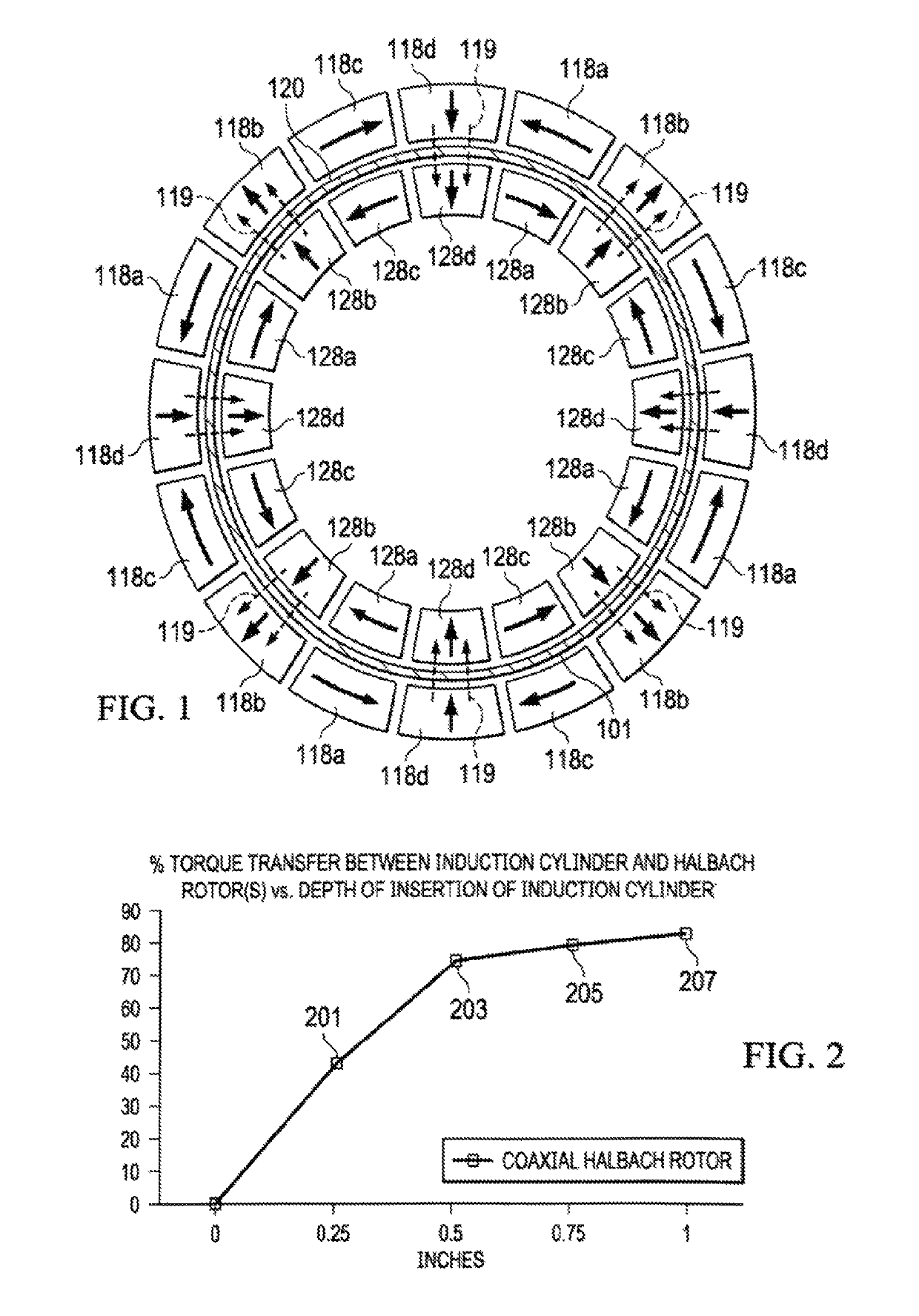
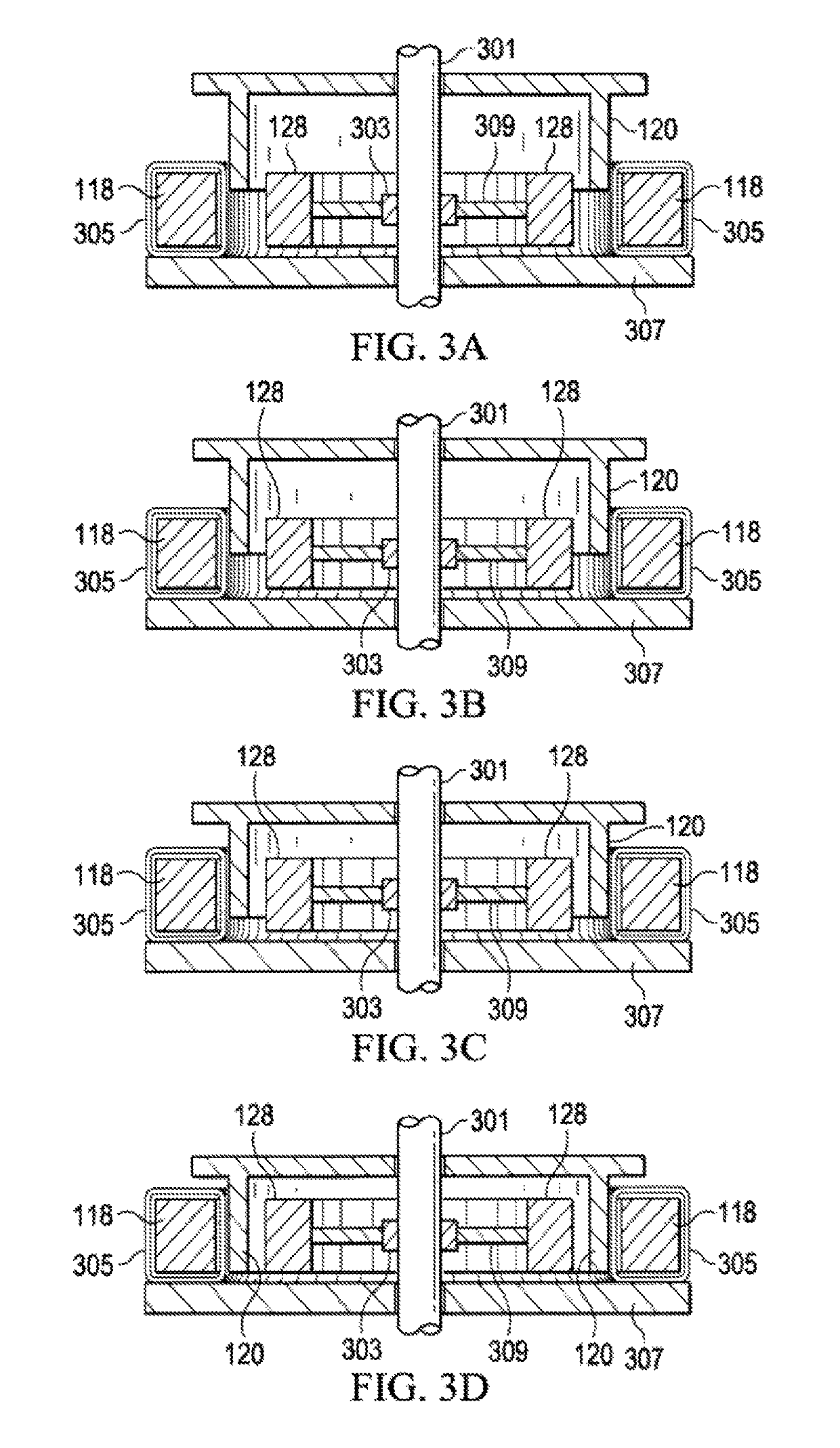
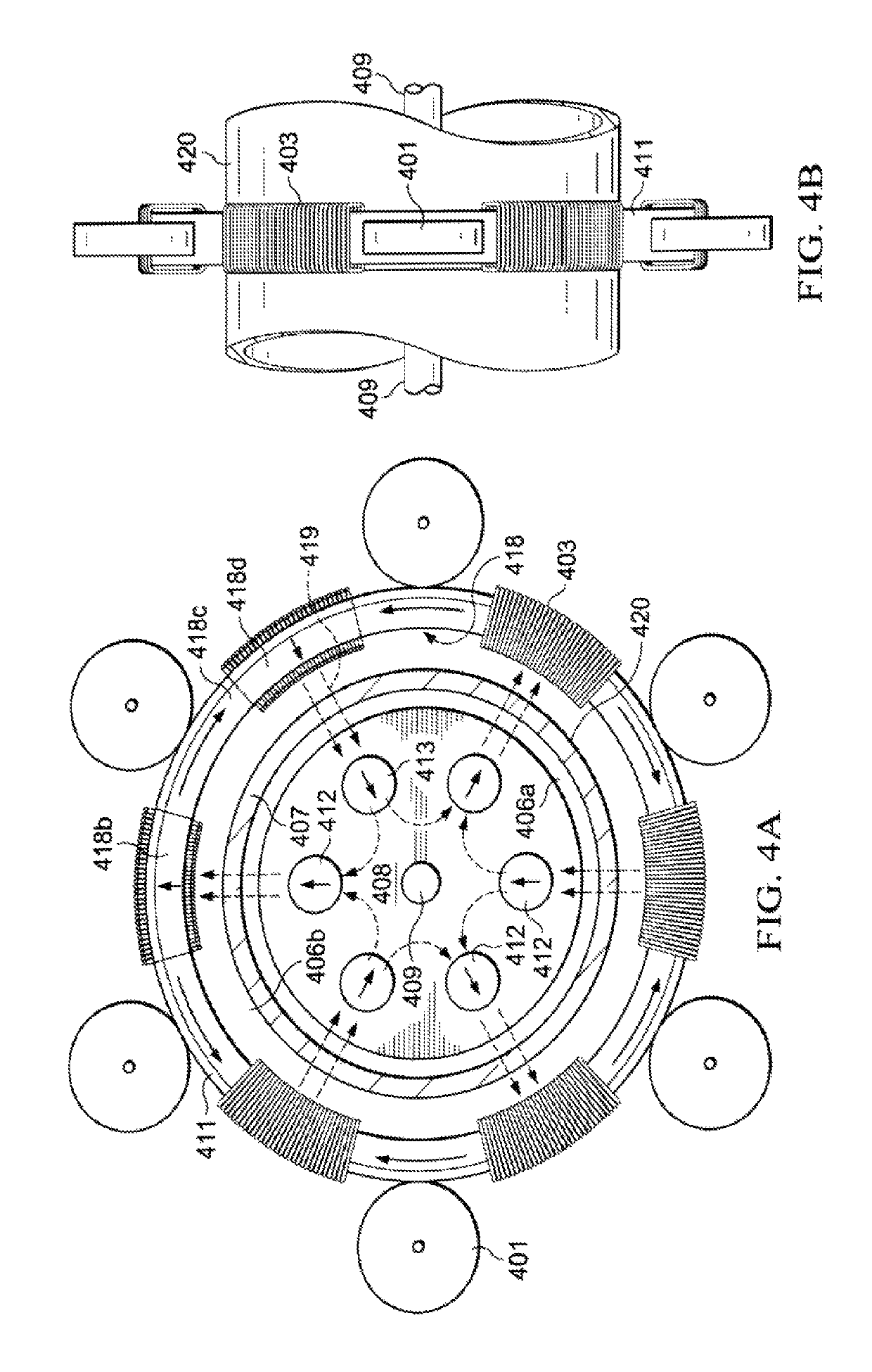
[0060]Refer now to the drawings wherein depicted elements are, for the sake of clarity, not necessarily shown to scale and wherein like or similar elements are designated by the same reference numeral through the several views. In the interest of conciseness, well-known elements may be illustrated in schematic or block diagram form in order not to obscure the present invention in unnecessary detail, and details concerning various other components known to the art, such as magnets, electromagnets, controllers, and the like necessary for the operation of many electrical devices, have not been shown or discussed in detail inasmuch as such details are not considered necessary to obtain a complete understanding of the present invention, and are considered to be within the skills of persons of ordinary skill in the relevant art.

[0061]In addition, as used herein, the term “substantially” is to be construed as a term of approximation. The term “N / S polarity” used with respect to a drawing, ...


PUM


Abstract

A flywheel energy storage device includes the Halbach Motor / Generator with rolling biphasic coil control, continuously variable torque transfer via magnetic induction and a reluctance magnetic levitation system known as the Axial-Loading Magnetic Reluctance Device. Electric energy input turns the magnetically coupled rotors of the Halbach motor, and torque is transferred to a flywheel through a copper cylinder variably inserted between the Halbach magnet rotors. In idle mode, the energy is stored kinetically in the spinning flywheel, which is levitated by a permanent magnet bearing. Electric energy output is achieved by transferring torque from the flywheel through the copper cylinder to the rotors of the Halbach Generator by magnetic induction. Rolling biphasic motor control includes dividing Halbach motor coils into increments, then energizing groups of contiguous increments into virtual coils, which revolve in tandem with the magnet rotors so to achieve continuous and optimal torque.

Description

CROSS-REFERENCE TO RELATED APPLICATIONS[0001]This application is a continuation-in-part of co-pending patent application Ser. No. 14 / 185,910 filed on Feb. 20, 2014, which issues as U.S. Pat. No. 9,876,407 on Jan. 23, 2018, and claims the benefit of:U.S. Provisional Application No. 61 / 766,705 filed Feb. 20, 2013,U.S. Provisional Application No. 61 / 891,829, filed Oct. 16, 2013,U.S. Provisional Application No. 61 / 892,019, filed Oct. 17, 2013,U.S. Provisional Application No. 61 / 894,489, filed Oct. 23, 2013,U.S. Provisional Application No. 61 / 895,115, filed Oct. 24, 2013,U.S. Provisional Application No. 61 / 899,204, filed Nov. 2, 2013,U.S. Provisional Application No. 61 / 906,136, filed Nov. 19, 2013, and[0002]U.S. Provisional Application No. 61 / 906,703, filed Nov. 20, 2013, and this application is also a continuation-in-part of U.S. patent application Ser. No. 14 / 523,687, filed Oct. 24, 2014, and published Apr. 30, 2015, as U.S. Pat. Pub. No. US 2015-0115756 A1, which claims the benefit of...

Claims


Application Information

Patent Timeline
Patent Type & Authority Patents(United States)
IPC IPC(8): H02K7/02H02K7/09F04D25/06F16C32/04F04D13/06F03G3/08
CPCH02K7/025H02K7/09F03G3/08F04D13/06Y02E60/16F05D2260/43F16C32/0417F16C2361/55F04D25/06
Inventor WALSH, RAYMOND JAMES
Owner WALSH RAYMOND JAMES
Why Eureka
Try Eureka