Passive method for controlling and correcting energy correlations in charged particle beams

a charged particle and energy correlation technology, applied in the direction of accelerators, laser details, electrical devices, etc., can solve the problems of ineffective attempts to operate the rf cavity beyond the crest after the final bunch compressor, high energy consumption, and high energy consumption, so as to improve the performance of many linear accelerator applications, improve beam quality, and improve the effect of beam quality

Active Publication Date: 2019-07-16
EUCLID TECHLABS LLC
View PDF9 Cites 0 Cited by
  • Summary
  • Abstract
  • Description
  • Claims
  • Application Information

AI Technical Summary

Benefits of technology

[0015]It is a feature of the present invention to provide an improved dielectric rf cavity or resonator through which a charged particle beam is passed in which during its passage the beam emits Cherenkov radiation (wakefield) that couples to the modes of the cavity. By appropriate design of the cavity (selection of the dielectric permittivity of the loading material, beam channel size, size of the dielectric and length of the structure) part of the energy of the leading portion of the bunch can be made to be absorbed by the trailing portion, thus equalizing the energy within the bunch.
[0016]Briefly described according to one embodiment of the present invention, a technology for the basis of a passive (not requiring an external source of rf) device for redistributing energy within a charged particle bunch to remove a spatial energy correlation within the bunch. A short relativistic electron bunch is passed through a planar or cylindrical dielectric cavity. By appropriate design of the cavity an undesirable head-tail energy correlation of the electron bunch can be compensated by transferring energy from the head to the tail by means of the wakefield in the cavity. The characteristics of this device are controllable by changing the aperture (for a planar configuration) or modifying the dielectric properties of the cavity through the use of an electrical or thermally controlled ferroelectric layer. Further, the need to compensate the difference between the energy of the head and tail regions of a charged particle bunch can improve the performance of many linear accelerator applications but is especially relevant for achieving the design requirements of X-Ray free electron lasers.
[0017]The application of this technology is for improving the beam quality of any type of linear accelerator. Some specific examples are (1) superconducting rf (SRF) electron linacs used to power X-Ray free electron lasers: the undesirable energy “chirp” of the electron beam that limits the performance of the XFEL can be eliminated over short distances of 10-20 cm by this invention; (2) laser plasma accelerators where the extremely short wavelengths involved tend to produce electron beams with large energy spread and very strong longitudinal correlations. The invention and also provides fine tuning of the basic correction parameters (wakefield magnitude and profile).
[0018]In accordance with a preferred embodiment, the aim of said invention is to enable the reduction of the position-correlated energy spread within a short electron bunch produced by a linear accelerator and that in turn would considerably improve the performance of an X-Ray free electron laser employing the corrected electron beam as a power source.

Problems solved by technology

Demands on the electron beam needed to drive this class of FELs are very challenging with present technologies.
This requirement is particularly challenging for L-Band linacs, where the wakefields are reduced compared to normal-conducting S-Band linacs and cannot be used to remove the energy chirp.
Attempts to operate the RF cavities beyond-crest after the final bunch compressor have also proved ineffective due to the short bunch length.
The reduced wakes of the SRF linac do not allow compensation of the energy spread that is left over at the output of the last compressor for wakefield effects through the rest of the accelerating stage.
While workable, this solution adds considerably to the overall cost of the linac.
In such embodiments, the use of existing technologies to eliminate the energy chirp involves increased cost and complexity of the system.
This is particularly problematic for the use of XFELs as turnkey research instruments.
Further, present technology methods for beam energy correction lack flexibility in adapting to a range of beam lengths and energy profiles, required for optimization of system performance.
Further still, the paucity of control options in existing compensation schemes impacts maintenance of long term system stability and hence accuracy and replicability of user measurements.

Method used


Image

  • Passive method for controlling and correcting energy correlations in charged particle beams
  • Passive method for controlling and correcting energy correlations in charged particle beams

Examples


Embodiment Construction

[0034]Briefly described according to a broad embodiment of the present invention, geometric configurations and methods of adjusting the characteristics of the aforementioned device are provided. The best mode for carrying out the invention is presented in terms of its preferred embodiment, herein depicted within the Figures.

[0035]1. Detailed Description of the Figures

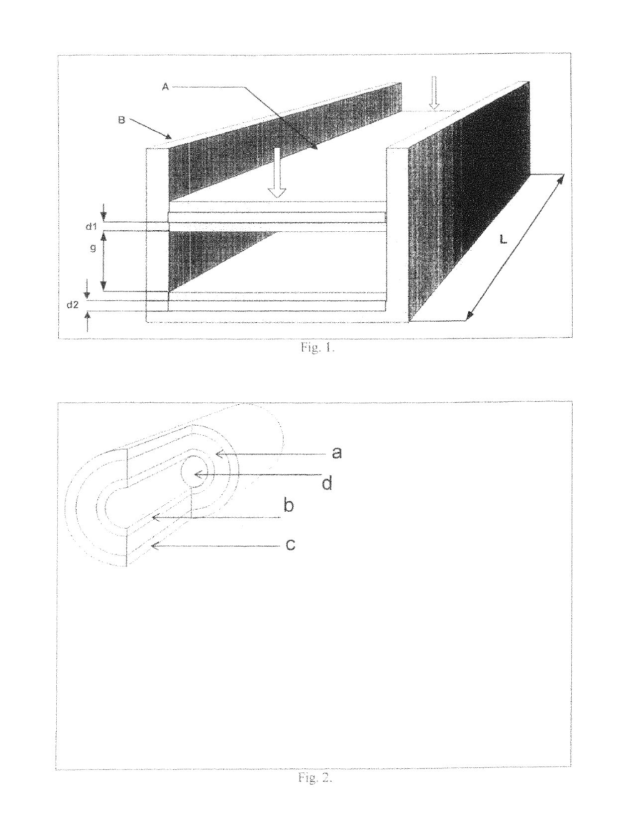
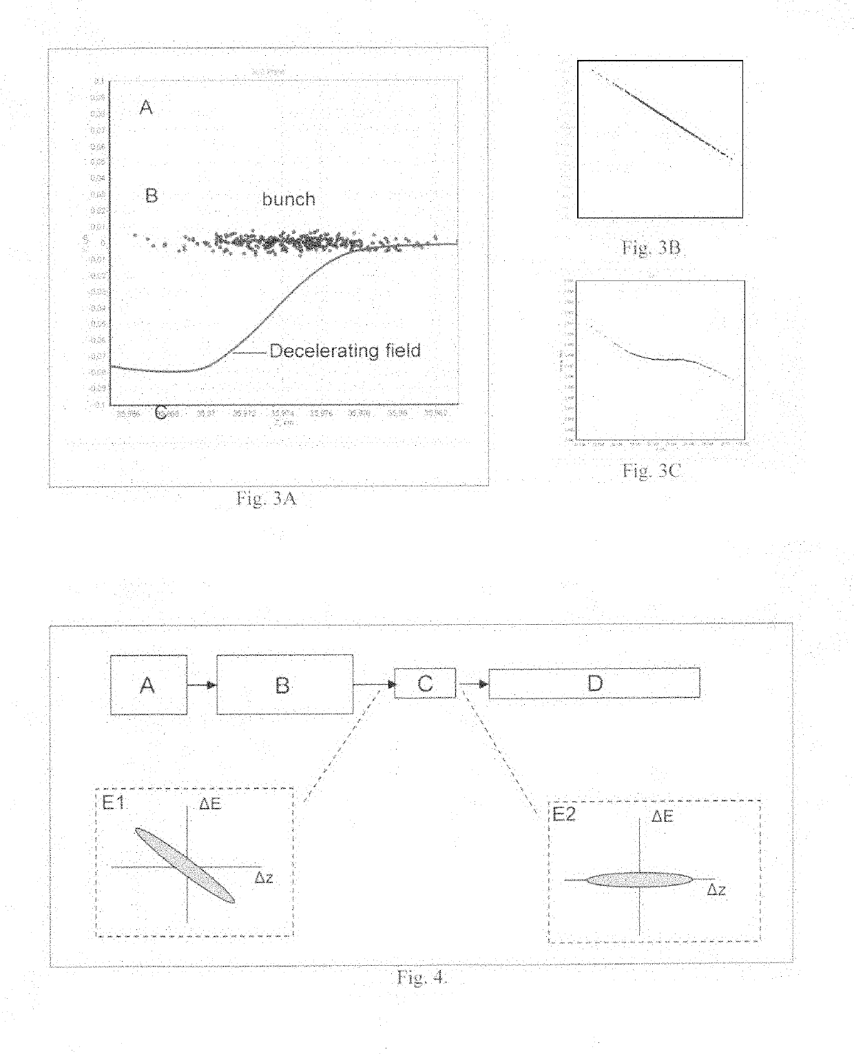
[0036]A wakefield is the electromagnetic wave emitted by a charged particle passing through a resonant structure. In the case of the dielectric loaded cavities considered here the radiation is emitted via the Cherenkov effect. The radiation couples to the resonant modes of the cavity. In the case of a charged particle bunch the wakefields of the particles add collectively. Particles in the bunch experience different retarding or accelerating forces depending on their relative positions within the bunch. The magnitude and sign of the force on a given particle depends on a number of factors: the total charge of the bunch;...


PUM


Abstract

A technique for controlling and compensating the energy spread of a charged particle beam is provided. This technique is based on a passive dielectric-loaded structure that redistributes the energy within the bunch by means of the wakefield generated in the structure. Cylindrical and planar structure configurations are provided and also means for electrical and mechanical tuning to optimize performance. The instant abstract is neither intended to define the invention disclosed in this specification nor intended to limit the scope of the invention in any way.

Description

RELATED APPLICATIONS[0001]The present application claims benefit of U.S. Ser. No. 61 / 724,440, filed on Nov. 9, 2012 and incorporated by reference as if fully rewritten herein.STATEMENT AS TO RIGHTS TO INVENTIONS MADE UNDER FEDERALLY-SPONSORED RESEARCH AND DEVELOPMENT (IF ANY)[0002]This invention was made with government support under a contract awarded by the Department of Energy, grant number DE-SC00011960. The government has certain rights in the invention.BACKGROUND OF THE INVENTION[0003]1. Technical Field of the Invention[0004]The present invention relates generally to the technical field of particle accelerator design and engineering and, in particular, to a method for controlling and correcting energy correlations in charged particle beams for high performance linear accelerators.[0005]2. Description of the Related Art[0006]Short, subpicosecond pulses are central to many of the next generation light source initiatives that are typical of linear accelerators. The free electron ...

Claims


Application Information

Patent Timeline
Patent Type & Authority Patents(United States)
IPC IPC(8): H05H7/00H05H9/00H01S4/00
CPCH05H7/001H05H9/00H01S4/00H05H2007/004H05H7/18H05H2007/122H01S3/0903
Inventor SIMPSON, JAMESROSING, MICHAELZHOLENTS, ALEXANDERANTIPOV, SERGEYJING, CHUNGUANGSCHOESSOW, PAULKANAREYKIN, ALEXEI
Owner EUCLID TECHLABS LLC
Why Eureka
Try Eureka