Timing synchronization for a beam hopping satellite

a satellite and beam hopping technology, applied in the field of timing synchronization of beam hopping satellites, can solve the problems of frequency reuse patterns that might not allow the flexibility of switching, synchronization errors, and synchronization to fail after acquisition

Active Publication Date: 2019-07-23
HUGHES NETWORK SYST
View PDF12 Cites 5 Cited by
  • Summary
  • Abstract
  • Description
  • Claims
  • Application Information

AI Technical Summary

Benefits of technology

[0005]This Summary is provided to introduce a selection of concepts in a simplified form that is further described below in the Detailed Description. This Summary is not intended to identify key features or essential features of the claimed subject matter, nor is it intended to be used to limit the scope of the claimed subject matter.

Problems solved by technology

One challenge in such a system is to synchronize the satellite switching with the ground network.
In some embodiments, the frequency reuse patterns might not allow the flexibility of switching at different times, and the switching times might have to be synchronized to the same instant.
A source of timing synchronization error after initial acquisition may be tracked.
There may be multiple sources of timing drift in a satellite network that cause the synchronization to fail after acquisition if no tracking mechanism present.
These errors might add destructively or constructively.
Although a geostationary satellite appears to be stationary over the earth, its relative position is not completely fixed.
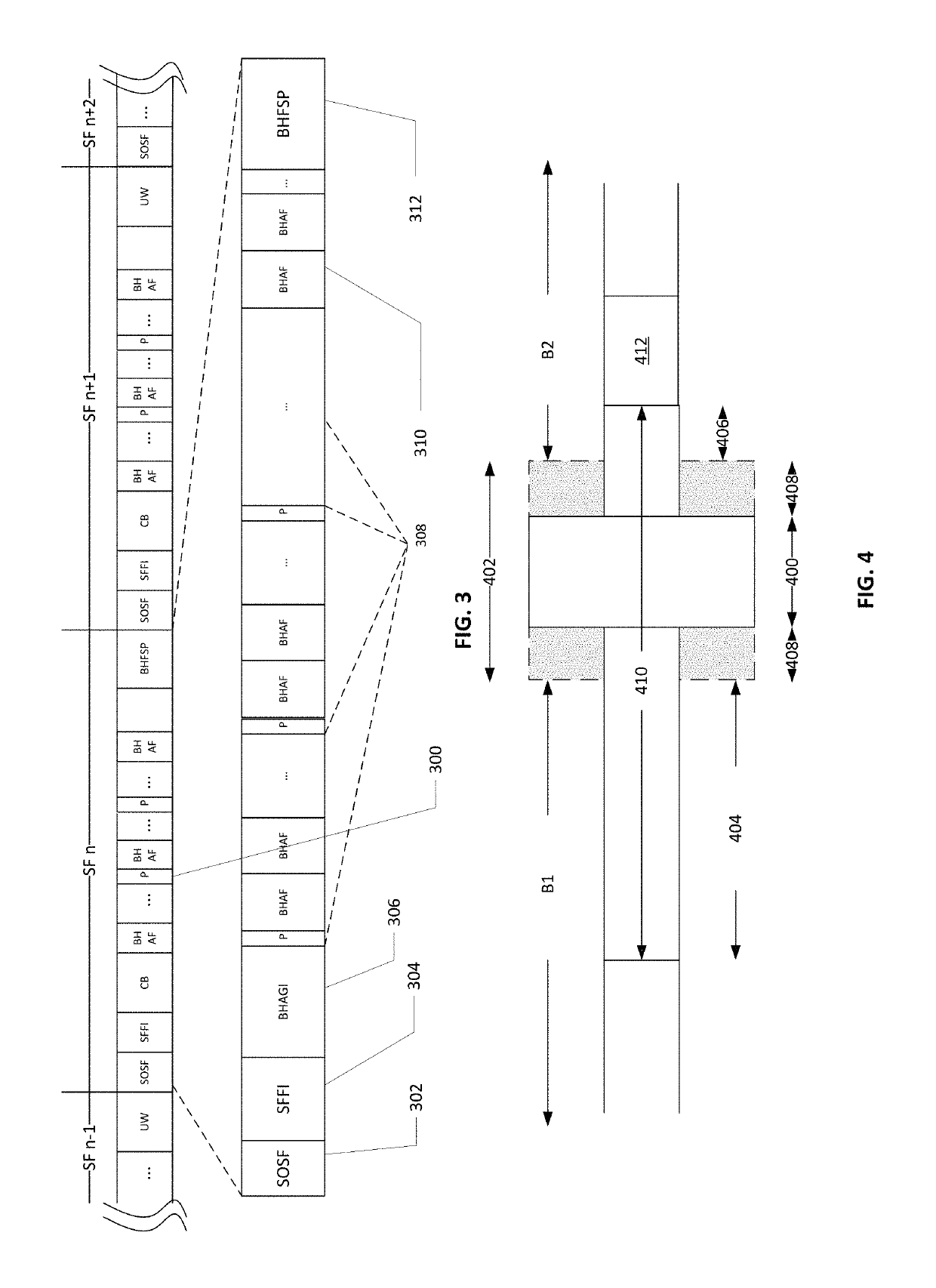
This may result in the SOSF markers of the Outroute arriving late and may be no longer synchronized with the satellite switching time.
If the satellite was moving towards the gateway, then the signal may arrive earlier at the satellite and again cause misalignment.
Since the satellite is constantly moving, there may be a drift in the alignment error correction.
On the Outroute, the change in timing in Gateway to satellite path may cause the error.
Any differences between the satellite clock may cause misalignment to the time synchronization in a similar fashion as the satellite motion.
In some embodiments, a resolution of the satellite clock duration or the frequency of the clock may introduce a timing error.
If there is a mismatch between the two, the result may be a shift in the alignment between the Outroute and Satellite switching instants.
The satellite to GW delay and terminal to satellite delay may impact the feedback loop.
This may add another delay to the gateway to satellite to terminal delay.
Adjacent beam interference in a beam hopping system may impact performance and synchronization.
Since the first and last BHRSP received during the satellite dwell time in a beam might not be received completely, it may result in a partial peak.
There may be an estimation error in the calculation of received BHRSP symbols.
Maintaining system capacity while it is raining on the gateway beam is challenging.
Since the location of the secondary or backup RFT and the Doppler due to the satellite motion may be different, the path delays between Gateway and satellite may change.
This will introduce an error in the timing since the actual satellite position is different than CoB.
This may initially introduce an error that may be offset by increasing the length of the guard time at the beginning of each of the switching times.
An error in timing for the backup gateway may be larger as compared to the primary gateway, as the backup GW is typically remote from the primary gateway.
This can result in the BHFSP length to change drastically.
The error in the TRO calculation even if using the new THSH may have an error that cannot be tolerated in steady state mode.

Method used


Image

  • Timing synchronization for a beam hopping satellite
  • Timing synchronization for a beam hopping satellite
  • Timing synchronization for a beam hopping satellite

Examples


Embodiment Construction

[0026]Embodiments are discussed in detail below. While specific implementations are discussed, this is done for illustration purposes only. A person skilled in the relevant art will recognize that other components and configurations may be used without parting from the spirit and scope of the subject matter of this disclosure.

[0027]The terminology used herein is for describing particular embodiments only and is not intended to be limiting of the present disclosure. As used herein, the singular forms “a,”“an” and “the” are intended to include the plural forms as well, unless the context clearly indicates otherwise. Furthermore, the use of the terms a, an, etc. does not denote a limitation of quantity but rather denotes the presence of at least one of the referenced item. The use of the terms “first,”“second,” and the like does not imply any order, but they are included to either identify individual elements or to distinguish one element from another. It will be further understood tha...


PUM


Abstract

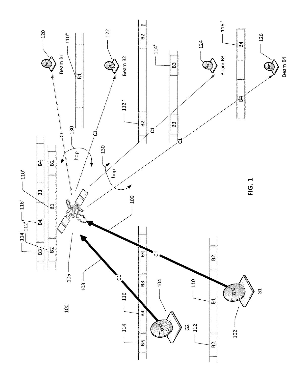
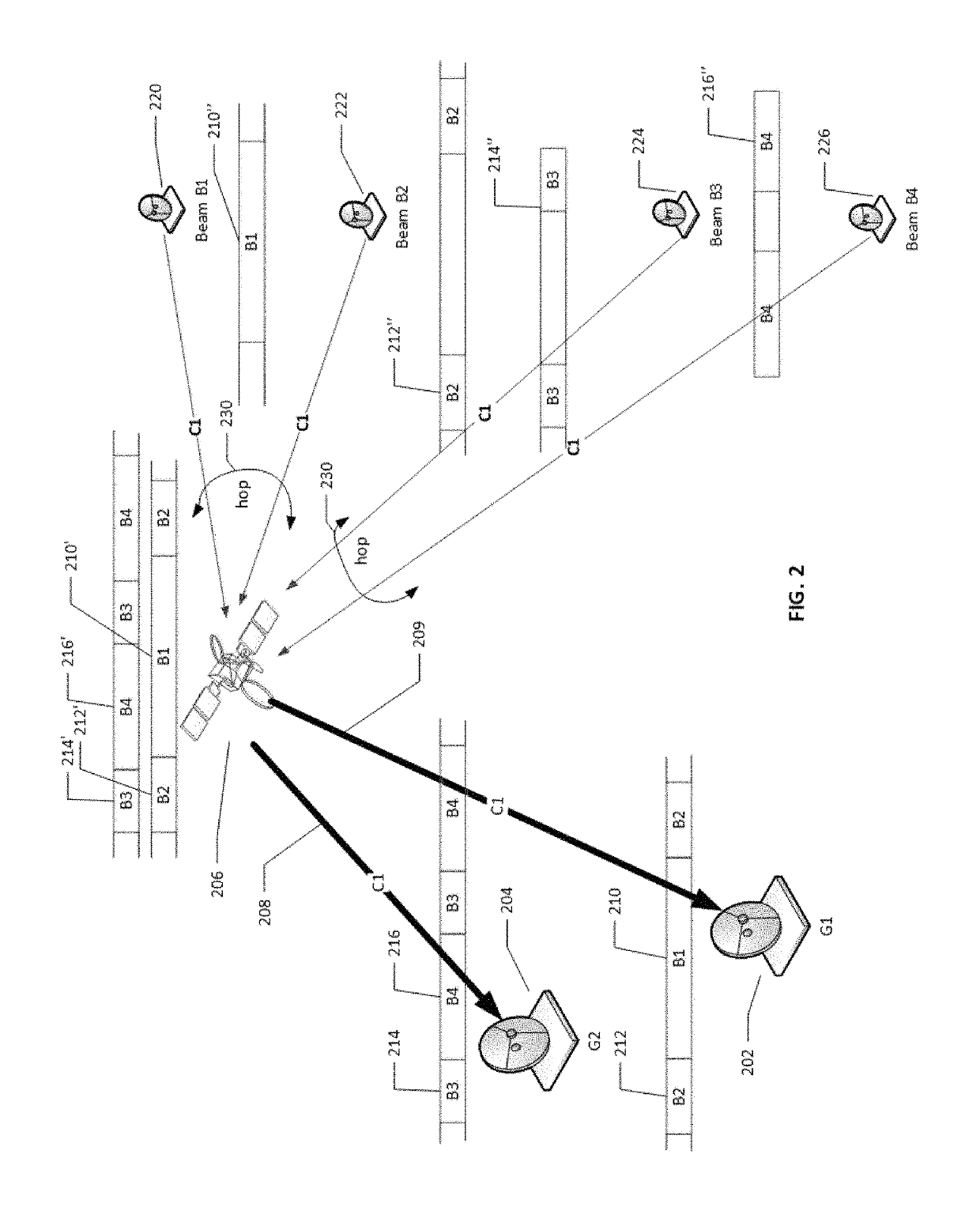
A system and method for timing synchronization of satellite switching instants with gateway switching instants is described. The method includes: generating satellite switching instants according to a Beam Hopping Time Plan (BHTP); generating gateway switching instants according to the BHTP; transmitting a channel addressed to a plurality of beams hopped according to the BHTP based on the gateway switching instants, wherein each of the plurality of beams includes a signal including timing markers and a guard period at an end of the signal for the respective beam; receiving a synchronization information, without a loopback beam, for one of the plurality of beams; determining an adjustment period and an adjusted symbol rate for the generating of the gateway switching instants, based on the synchronization information, for a transmission of the channel such that at least a portion of the guard period in a respective signal for a respective beam aligns with one of the satellite switching instants; and adjusting a timing and a symbol rate of the transmission according to the adjustment period and the adjusted symbol rate, respectively.

Description

CROSS REFERENCE TO RELATED APPLICATIONS[0001]The present application claims the benefit of U.S. Provisional Patent Application Nos. 62 / 610,506 and 62 / 610,507, both filed Dec. 26, 2017, and both of which are incorporated herein in their entireties.FIELD[0002]The present teachings describe timing synchronization of a beam hopping satellite with a terrestrial clock. The synchronization involves transmitting a waveform including timing markers, a synchronization pattern and other relevant information to a user terminal that provides feedback information to achieve and maintain timing synchronization between the gateway switching instants and the switching instants of the satellite. In some embodiments, different waveforms are used in the phases of achieving synchronization (acquisition) and maintaining synchronization (tracking).BACKGROUND[0003]Beam hopping dynamically changes routing of an uplink spectrum (or a portion of it) to a downlink by a satellite. A beam hopping satellite may i...

Claims


Application Information

Patent Timeline
Patent Type & Authority Patents(United States)
IPC IPC(8): H04B7/185H04W28/18H04B7/204H04W72/04H04L27/26H04B7/06H04L7/00
CPCH04B7/18513H04B7/0617H04B7/18515H04B7/2041H04L27/2655H04W28/18H04W72/046H04L7/0008H04B7/2048H04B7/18523
Inventor REGUNATHAN, MURALIANTIA, YEZDIBECKER, NEAL DAVIDKAY, STANLEYBHASKAR, UDAY R.
Owner HUGHES NETWORK SYST
Why Eureka
Try Eureka