Supercharge Your Innovation With Domain-Expert AI Agents!

Restrictive up flow media filter with servicing system

a filter and media filter technology, applied in the field of water detention and treatment, can solve the problems of fines, slow filtration rate to an ineffective flow rate, and limited reactivity of the media surface,

Active Publication Date: 2019-08-20
OLDCASTLE INFRASTRUCTURE INC
View PDF53 Cites 6 Cited by
  • Summary
  • Abstract
  • Description
  • Claims
  • Application Information

AI Technical Summary

Benefits of technology

The present invention provides vultures, boxes, systems, and methods of treatment to capture and prevent the conveyance of pollutants from storm water runoff. The system includes multiple stages and processes for the treatment of water shed from an area as a result of rain. It offers an easy and inexpensive method for serving the media, without having to remove or replace the media. The system includes a vault with a settling chamber, a media bed, and a bypass flow to allow for the flow of water through the media. It also includes a spray system to remove solids from the vault during servicing. The invention prevents the conveyance of a wide spectrum of pollutants from being conveyed to a receiving body of water or landscape area, and enhances the removal efficiency of almost any type of filtration media by increasing contact time between the media and the pollutants.

Problems solved by technology

The result of exceeding these numeric values will result with the state of Florida being fined by the EPA.
A difficulty with physical filtration is that the collected solids can become so numerous that the rate of filtration is slowed to an ineffective flow rate.
However, the reactivity of the media surfaces is limited by the number of receptors on the surface of the media.
However, the smaller the granular size of the media the more likely the media will be to bind due to the collection of solids within the media.
However, a difficulty with having a biofilm consume the nutrients is that the biofilm will require adequate time to consume the nutrients.

Method used


Image

  • Restrictive up flow media filter with servicing system
  • Restrictive up flow media filter with servicing system
  • Restrictive up flow media filter with servicing system

Examples


first embodiment

Upflow Media Filter with Sloped Floors and Hydroslide

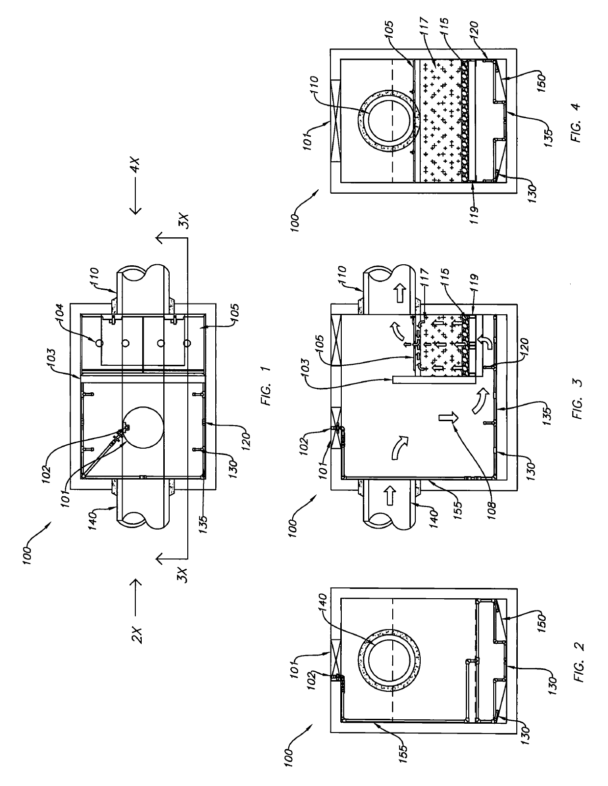
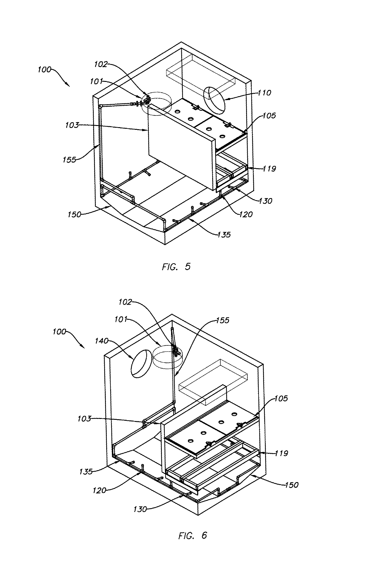
[0144]FIG. 1 is a top view of the upflow media filter baffle box / vault 100 with sloped floors 150 and hydroslide. FIG. 2 shows an inflow end view of the upflow media filter baffle box / vault 100 of FIG. 1 along arrow 2X with flow directional arrows. FIG. 3 is a side cross-sectional view of the upflow media filter baffle box / vault 100 of FIG. 1 along arrows 3X. FIG. 4 is an outflow view of the upflow media filter baffle box / vault 100 of FIG. 1 along arrow 4X. FIG. 5 is an upper partial front right perspective view of the upflow media filter baffle box / vault 100 of FIG. 1. FIG. 6 is an upper partial rear left perspective view of the upflow media filter baffle box / vault 100 of FIG. 1 without gravel / rock layer 115, media 117, top screen 105 and bottom screen 119.

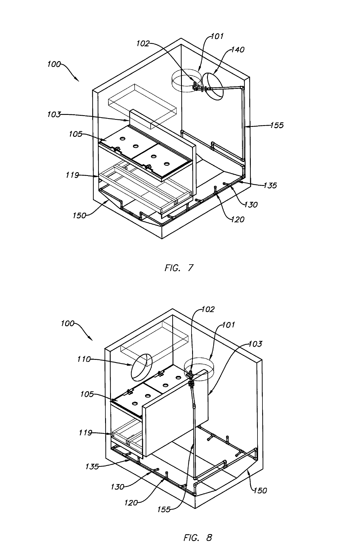
[0145]FIG. 7 is an upper partial rear right perspective view of the upflow media filter baffle box / vault 100 of FIG. 1 without gravel / rock layer 115, media 117, top screen 105 ...

second embodiment

Upflow Media Filter with Plastic Lids with Screened Orifice Opened for Servicing

[0170]FIG. 11 is another side view of the upflow media filter baffle box / vault 200 of FIG. 3 with one open lid 206 and servicing hose 207 and back-flush directional flow. FIG. 12 is an upper partial front right perspective view of the upflow media filter baffle box / vault 200 of FIG. 11 without gravel / rock layer 215, media 217 and screen 219. FIG. 13 is an upper partial rear left perspective view of the upflow media filter baffle box / vault 200 of FIG. 11 without gravel / rock layer 215, media 217 and screen 219. FIG. 14 is an upper partial rear right perspective view of the upflow media filter baffle box / vault 200 of FIG. 11 without gravel / rock layer 215, media 217 and screen 219. FIG. 15 is an upper partial front left perspective view of the upflow media filter baffle box / vault 200 of FIG. 11 without gravel / rock layer 215, media 217 and screen 219.

[0171]Referring to FIGS. 11-15, components 202, 203, 204, 2...

third embodiment

Upflow Media Filter with Floating Skimmer

[0177]FIG. 16 is a top view of the upflow media filter baffle box / vault / system 300 of FIG. 1 with floating skimmer 311. FIG. 17 is an inflow view of the upflow media filter baffle box / vault 300 of FIG. 16 along arrow 17X FIG. 18 is side cross-sectional view of the upflow media filter baffle box / vault 300 of FIG. 16 along arrow 18X. FIG. 19 is an outflow view of the inflow media filter baffle box / vault 300 of FIG. 16 along arrow 19X. FIG. 20 is an upper partial front right perspective view of inflow media filter baffle box / vault 300 of FIG. 16 without gravel / rock layer 315, media 317 and bottom screen 319. FIG. 21 is an upper partial rear left perspective view of inflow media filter baffle box / vault 300 of FIG. 16 without gravel / rock layer 315, media 317 and bottom screen 319. FIG. 22 is an upper partial rear right perspective view of inflow media filter baffle box / vault 300 of FIG. 16 without gravel / rock layer 315, media 317 and bottom screen...


PUM

PropertyMeasurementUnit
Fractionaaaaaaaaaa
Thicknessaaaaaaaaaa
Pressureaaaaaaaaaa

Abstract

Vaults, boxes, chambers, systems, and methods of treatment systems to capture pollutants from storm water runoff and prevent the conveyance of these pollutants from entering a receiving water body or landscape area, which is designed to be a part of a local permanent storm water drainage infrastructure. The system enhances the removal efficiency of almost any type of filtration media by increasing contact time between storm water runoff and the media, and also offers an easy and inexpensive method for serving the media, without having to remove or replace the media. A media filter can include a bottom screen, a media layer, and at least one top lid that can be opened to allow for backwashing of the media layer without removing the media layer from the filter. A servicing system can include pivotal spray heads to pivot to parallel positions over a sloped floor to flush debris toward easy to reach locations to be vacuumed, and vertical spray heads which can break up debris bridges.

Description

CROSS REFERENCE TO RELATED APPLICATIONS[0001]This application is a Continuation In Part of U.S. patent application Ser. No. 15 / 639,685 filed Jun. 30, 2017, now allowed, which claims the benefit of priority to U.S. Provisional Patent Application Ser. No. 62 / 506,188 filed May 15, 2017, and this application is a Continuation In Part of U.S. patent application Ser. No. 14 / 288,455 filed May 28, 2014, now abandoned, which claims the benefit of priority to U.S. Provisional Application Ser. No. 61 / 828,958 filed May 30, 2013. The entire disclosure of each of the applications listed in this paragraph are incorporated herein by specific reference thereto.FIELD OF INVENTION[0002]This invention relates to water detention and treatment, and in particular to vaults, boxes, systems, and methods of treatment systems to capture pollutants from storm water runoff and prevent the conveyance of these pollutants from entering a receiving water body or landscape area, which is designed to be a part of a l...

Claims


Application Information

Patent Timeline
IPC IPC(8): E03F5/14C02F1/00B01D24/26B01D21/24C02F1/40B01D21/00C02F1/28C02F3/06B01D24/46C02F3/00C02F103/00
CPCC02F1/004C02F1/40C02F1/28C02F3/06B01D24/263B01D24/4621B01D24/4631E03F5/14B01D21/2472B01D21/0012C02F2103/001C02F2303/16C02F2003/001C02F1/001C02F2201/002B01D24/165
Inventor HAPPEL, TOM
Owner OLDCASTLE INFRASTRUCTURE INC
Features
  • R&D
  • Intellectual Property
  • Life Sciences
  • Materials
  • Tech Scout
  • Unparalleled Data Quality
  • Higher Quality Content
  • 60% Fewer Hallucinations
Learn More