Image processing device, imaging device, image processing method, and image processing program

a technology of image processing and imaging device, applied in image enhancement, camera filters, instruments, etc., can solve problems such as inability to satisfactorily perform point image restoration, and achieve good point image restoration

Active Publication Date: 2019-08-27
FUJIFILM CORP
View PDF32 Cites 0 Cited by
  • Summary
  • Abstract
  • Description
  • Claims
  • Application Information

AI Technical Summary

Benefits of technology

[0012]Further, the focal position adjustment device described in JP2010-230776A performs contrast autofocus (AF) with high accuracy in a short time using the focal position shift due to the chromatic aberration (visible light and near-infrared light) of the lens in the camera capable of simultaneously acquiring a visible light image and a near-infrared light image. JP2010-230776A does not describe performing point image restoration on an originally captured visible light image or near-infrared light image, and does not disclose a problem in a case where the point image restoration process is performed on a near-infrared light image captured at twilight or dawn.
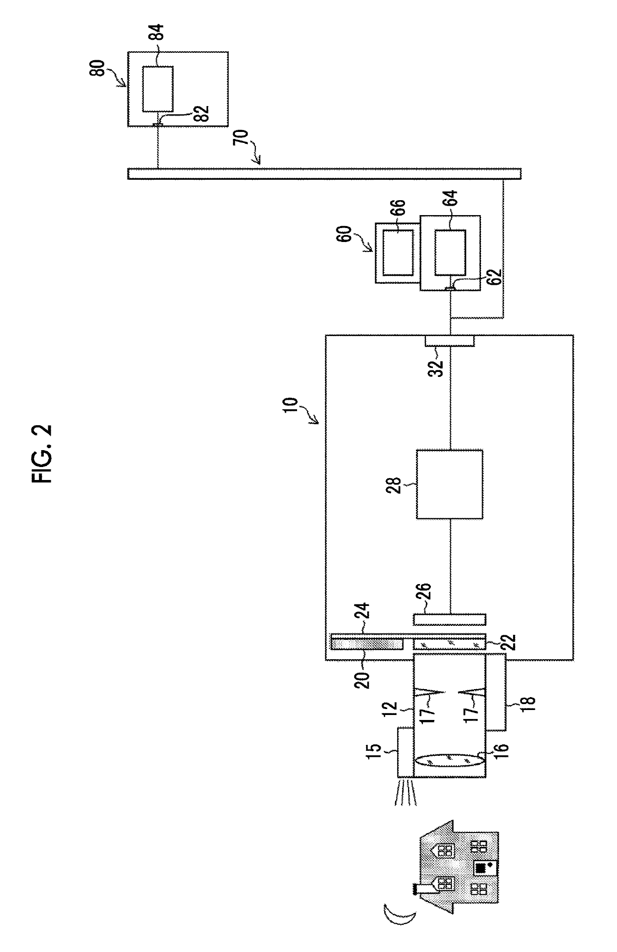
[0028]Accordingly, it is possible to satisfactorily perform the point image restoration process on the image data of only the near-infrared light component that is captured in nighttime. A case where the acquired image data is the image data of only the near-infrared light component is, for example, a case where a light amount ratio of the visible light detected by the light amount ratio detection unit is very low. The amount of visible light is not limited to 0 and is 10% or less, preferably 5% or less, and more preferably, 3% or less of the total amount of light.

Problems solved by technology

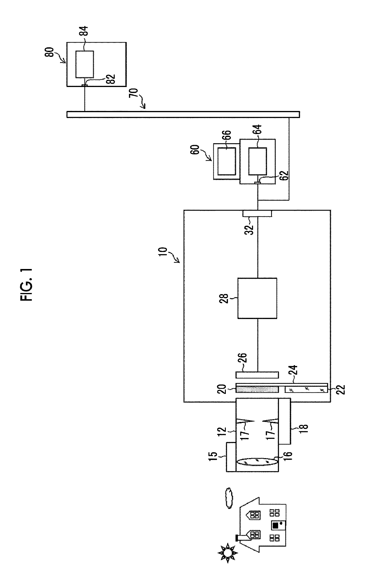
However, actually, since there is time in which the visible light and the near-infrared light coexist at the time of switching from daytime to nighttime (so-called twilight state) and the time of switching from nighttime to daytime (so-called dawn state), the point image restoration cannot be satisfactorily performed even when any one of the point image restoration filter for visible light and the point image restoration filter for near-infrared light is used for the near-infrared light image captured in a twilight and dawn state.
JP2008-113704A discloses problems that a calculation coefficient for a restoration process (convolution calculation) is changed when each of the dispersed images of a visible light image and a near-infrared light image captured using a depth of field extension optical system having an optical wavefront modulation element is restored, and a focal length is different according to a wavelength of the visible light and the near-infrared light in a case where the visible light image and the near-infrared light image are captured using one imaging system, but does not disclose a configuration in which a subject is imaged under a light source (twilight or dawn) in which visible light and near-infrared light coexist, or a problem in a case where a point image restoration process is performed on a near-infrared light image captured at twilight or dawn.
JP2010-230776A does not describe performing point image restoration on an originally captured visible light image or near-infrared light image, and does not disclose a problem in a case where the point image restoration process is performed on a near-infrared light image captured at twilight or dawn.

Method used


Image

  • Image processing device, imaging device, image processing method, and image processing program
  • Image processing device, imaging device, image processing method, and image processing program
  • Image processing device, imaging device, image processing method, and image processing program

Examples


first embodiment

of Image Processing Method

[0115]FIG. 9 is a flowchart illustrating a first embodiment of the image processing method according to the present invention, and illustrates a point image restoration processing operation in the point image restoration processing unit 48 of the first embodiment illustrated in FIG. 7.

[0116]In FIG. 9, the camera controller 28 detects the amount of light (for example, an EV value) of the subject, and discriminates whether the detected amount of light is equal to or larger than a threshold value Th (step S10). In a case where the detected amount of light is equal to or larger than the threshold value Th (“Yes”), the process proceeds to step S12 to switch the imaging mode to the visible light image capturing mode that is an imaging mode during daytime, and in a case where the detected amount of light is smaller than the threshold value Th (“No”), the process proceeds to step S18 to switch the imaging mode to the near-infrared light image capturing mode that is...

second embodiment

of Image Processing Method

[0158]FIG. 13 is a flowchart illustrating a second embodiment of the image processing method according to the present invention, and illustrates a point image restoration processing operation in the point image restoration processing unit 48 of the second embodiment illustrated in FIG. 12. In FIG. 13, steps of performing the same process as that illustrated in FIG. 9 are denoted with the same step numbers, and detailed description thereof will be omitted.

[0159]The image processing method illustrated in FIG. 13 is different in that a process of step S132 is performed in place of the processes of steps S30 and S32 illustrated in FIG. 9.

[0160]In step S132 illustrated in FIG. 13, the first PSF for visible light and the second PSF for near-infrared light are subjected to weighted averaging on the basis of the light amount ratio between the amount of visible light and the amount of near-infrared light detected by the light amount ratio detection unit 160 with res...

third embodiment

of Point Image Restoration Processing Unit

[0161]Next, a third embodiment of the point image restoration processing unit 48 illustrated in FIG. 6 will be described.

[0162]FIG. 14 is a block diagram illustrating a point image restoration processing unit 48 of the third embodiment. The same portions as those in the second embodiment illustrated in FIG. 12 are denoted with the same reference numerals, and detailed description thereof will be omitted.

[0163]The point image restoration processing unit 48 of the third embodiment illustrated in FIG. 14 is mainly different in that a third point spread function storage unit 260 is included in place of the third point spread function generation unit 240 illustrated in FIG. 12.

[0164]That is, the third PSF generated similarly to the third PSF that is generated by the third point spread function generation unit 240 illustrated in FIG. 12 is stored in the third point spread function storage unit 260 in association with the light amount ratio of the ...


PUM


Abstract

In a case where IR data of a near-infrared light image is data in which a visible light component and a near-infrared light component coexist, a point image restoration process is performed on the IR data using a first point image restoration filter based on a first point spread function for visible light of the optical system and a second point image restoration filter based on a second point spread function for near-infrared light of the optical system. An appropriate point image restoration process is performed on the IR data that is captured in a time zone of twilight or dawn by performing weighted averaging on a point image restoration process using the first point image restoration filter and a point image restoration process using the second point image restoration filter using a first gain α and a second gain β according to a light amount ratio between visible light and near-infrared light at the time of capturing the IR data.

Description

CROSS-REFERENCE TO RELATED APPLICATIONS[0001]The present application is a Continuation of PCT International Application No. PCT / JP2016 / 062169 filed on Apr. 15, 2016 claiming priority under 35 U.S.C §119(a) to Japanese Patent Application No. 2015-088228 filed on Apr. 23, 2015. Each of the above applications is hereby expressly incorporated by reference, in their entirety, into the present application.BACKGROUND OF THE INVENTION1. Field of the Invention[0002]The present invention relates to an image processing device, an imaging device, an image processing method, and an image processing program, and more particularly, to a technology for performing a point image restoration process on the basis of a point spread function on a visible light image and a near-infrared light image.2. Description of the Related Art[0003]A point spread phenomenon in which a point subject has small spread due to an influence such as diffraction or aberration caused by an optical system may be observed in a ...

Claims


Application Information

Patent Timeline
Patent Type & Authority Patents(United States)
IPC IPC(8): H04N5/33G03B11/00G06T5/00G02B5/20H04N5/232G06T5/20H04N5/225G03B15/00
CPCG03B11/00G03B15/00G06T2207/10048G02B5/208G06T5/003H04N23/661H04N23/667H04N23/80H04N23/11H04N25/131H04N25/135H04N23/843H04N25/134G06T5/20
Inventor TANAKA, JUNICHIHAYASHI, KENKICHINARUSE, YOUSUKE
Owner FUJIFILM CORP
Why Eureka
Try Eureka