Method and device for reducing the emissions of an internal combustion engine

a technology of internal combustion engine and emission reduction, which is applied in the direction of combustion engine, electric control, machines/engines, etc., can solve the problems of reducing the emission of nitrogen oxide, achieving the purification effect of the convertor, etc., and achieve the effect of reducing the emission

Active Publication Date: 2019-09-03
ROBERT BOSCH GMBH
View PDF6 Cites 1 Cited by
  • Summary
  • Abstract
  • Description
  • Claims
  • Application Information

AI Technical Summary

Benefits of technology

[0005]Therefore, it is an object of the present invention to provide a method for reducing the emission of hydrocarbons and nitrogen oxides in the start / catalytic converter heating phase of an internal combustion engine having externally supplied ignition.
[0007]The objective of the present invention with regard to the method may be achieved in that in a first phase of the start / catalytic converter heating phase, the internal combustion engine is operated using a lean air-fuel mixture in a range between a lambda value of 1.05 and a lean misfire limit of the internal combustion engine that lies at a higher lambda value, and / or in that in a second phase of the start / catalytic converter heating phase, it is initially operated using a rich air-fuel mixture having an initial value in a range between a lambda value of 0.95 and a lambda value of 0.995, and during the second phase, the lambda value of the air-fuel mixture is brought from the initial value to a lambda target value. As a result of this heating strategy for the heating of the catalytic converter, which is adapted to the behavior of the internal combustion engine and the catalytic converter, it is possible to reduce the raw emissions of hydrocarbons and nitrogen oxides in the first phase following the start of the internal combustion engine in the start / catalytic converter heating phase. Because of the precontrol or adjustment of a lambda value that is appropriate depending on the combustion method, in a range between 1.05 to 1.25, for example, the raw emissions of the internal combustion engine are reduced when compared with an operation in a lambda range of 1.0 to 1.05. As an upper limit of the lambda value, a drop below the lean misfire limit of the internal combustion engine must take place, which may typically lie at a lambda value of 1.25 depending on the precise operating conditions.
[0008]If the catalytic converter has been heated to such a degree that a sufficient conversion of the hydrocarbons and nitrogen oxides takes place, the nitrogen oxide emission is heavily reduced by the rapid switch to a rich air-fuel mixture at the beginning of the second phase, inasmuch as an abruptly increased conversion of the nitrogen oxide raw emissions takes place in the catalytic converter. The interaction between these two phases makes it possible to set a greater exhaust gas heat flow, so that more rapid heating is able to be achieved after the start. Overall, the method achieves a considerable reduction of the undesired emission of hydrocarbons and, in particular, nitrogen oxides. The lambda value to be set in the first phase depends on the combustion method and is adjusted to ensure a reliable ignition and combustion of the mixture. A model of the engine behavior with regard to raw emissions, exhaust gas heat flow and running behavior may be used to specify the mixture stoichiometry, which, in addition to considering suitable engine control signals (e.g., highly resolved engine speed, combustion chamber pressure), also takes effects of the fuel quality and engine aging into account. A smooth-running control is able to safeguard the adjustment of the lambda value permitted depending on the state of the combustion engine, the fuel quality and ambient conditions.
[0009]The two method components for the first and second phase may be used both jointly or each one separately by itself. The lean operation in the described development presupposes that the combustion method used in the particular case reliably allows such a lean operation immediately after the start. The use of the rich mixture in the second phase makes it possible to use more retarded ignition angles than in the related art, so that the torque reserve becomes greater and the heating of the exhaust gas is increased.
[0011]A minimal total emission is achieved by ending the first phase when the temperature of the catalytic converter is so high that the conversion of hydrocarbons and nitrogen oxides is higher than the reduction potential of raw emissions when using a lean fuel-air mixture.
[0015]The object of the present invention with regard to the device may be achieved in that a switching circuit or a program sequence is provided in the engine control for operating the internal combustion engine in the start / catalytic converter heating phase in a first phase using a lean air-fuel mixture, e.g., in a range between lambda=1.05 and a lean misfire limit of the internal combustion engine that is higher (e.g., lambda=1.25), and / or in a second phase using a rich air-fuel mixture having an initial lambda value in a range between, for example, lambda=0.95 and lambda=0.995 and a transition to a lambda target value. In Otto engines for lowest-emission concepts, the device according to the present invention advantageously makes it possible to heat the catalytic converter very rapidly after the engine start, and to thereby start the conversion of the raw emissions of the engine as rapidly as possible. Furthermore, the expelling of undesired nitrogen oxides is reduced in comparison with the related art due to the transition from the lean phase to the rich phase.

Problems solved by technology

However, catalytic converters achieve their purification effect only when heated to a sufficiently high temperature.
However, depending on the combustion method, this often has the result that a greater quantity of nitrogen oxide is contained in the exhaust gas as the exhaust gas temperature rises or an exhaust gas heat flow increases.

Method used


Image

  • Method and device for reducing the emissions of an internal combustion engine
  • Method and device for reducing the emissions of an internal combustion engine

Examples


Embodiment Construction

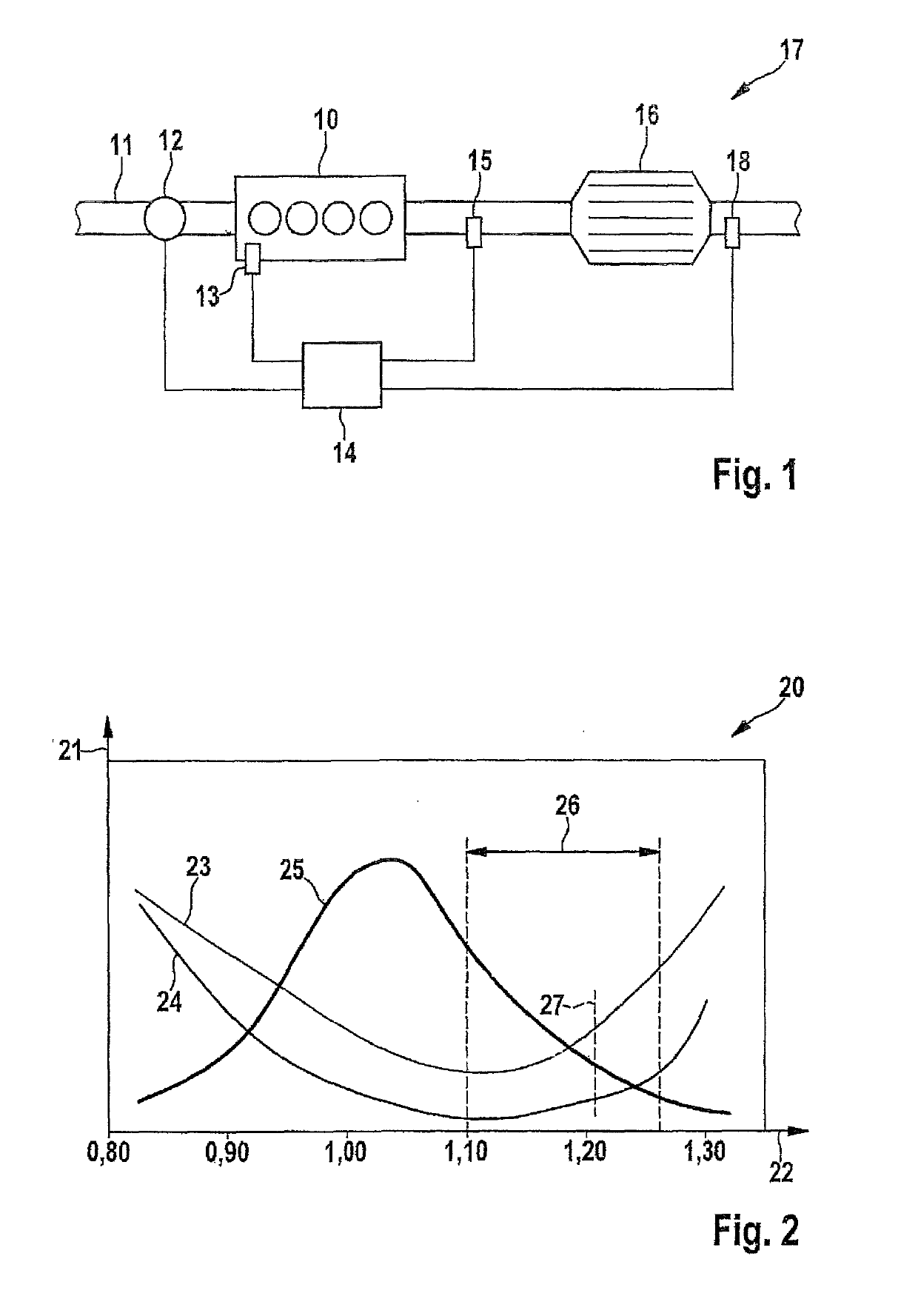
[0020]FIG. 1 schematically illustrates the technical environment in which the method of the present invention may be used. An internal combustion engine 10, which is realized as gasoline engine having externally supplied ignition, is supplied with combustion air via an air supply 11. By way of example, the air quantity of combustion air is able to be ascertained with the aid of an mass air flow meter 12 in air supply 11. The supplied air quantity is used for ascertaining the fuel quantity to be added at a lambda value to be precontrolled or adjusted, for ascertaining exhaust gas parameters such as an exhaust gas quantity, a volumetric flow or an exhaust-gas rate. The exhaust gas of internal combustion engine 10 is discharged via an exhaust duct 17, in which a catalytic converter 16 is situated. Furthermore, a first lambda probe 15 upstream from catalytic converter 16 and a second lambda probe 18 downstream from catalytic converter 16 are disposed in exhaust tract 17, whose signals a...


PUM


Abstract

A method for reducing the pollutant emissions in the exhaust gas in a start / catalytic converter heating phase of an internal combustion engine featuring externally supplied ignition and having at least one catalytic converter in an exhaust gas tract of the internal combustion engine, and for adapting a catalytic converter heating strategy to suitable state variables of the internal combustion engine and the catalytic converter as well as to the fuel quantity, the aging state and ambient conditions. The internal combustion engine is operated in a first phase of the start / catalytic converter heating phase using a lean air-fuel mixture in a range between a lambda value of 1.05 and at a lean misfire limit of the internal combustion engine that lies at a higher lambda value, and / or in a second phase of the start / catalytic converter heating phase, initially using a rich air-fuel mixture.

Description

RELATED APPLICATION INFORMATION[0001]The present application claims priority to and the benefit of German patent application no. 10 2013 221 595.9, which was filed in Germany on Oct. 24, 2013, the disclosure of which is incorporated herein by reference.FIELD OF THE INVENTION[0002]The present invention relates to a method for reducing the pollutant emissions in the exhaust gas in a start / catalytic converter heating phase of an internal combustion engine featuring externally supplied ignition and having at least one catalytic converter in an exhaust tract of the internal combustion engine, and for adapting a catalytic converter heating strategy to suitable state variables of the internal combustion engine and of the at least one catalytic converter as well as to the fuel quality, aging state and ambient conditions. The present invention furthermore relates to a device for reducing the pollutant emissions in the exhaust gas in a start / catalytic converter heating phase of an internal co...

Claims


Application Information

Patent Timeline
Patent Type & Authority Patents(United States)
IPC IPC(8): F02D41/02F02D41/06F02D41/14
CPCF02D41/024F02D41/062F02D41/0255F02D41/1475F02D2200/0802F02D41/1459F02D41/1463Y02T10/26Y02T10/12
Inventor HOFSTAETTER, JOCHENRICKEN, VOLKER
Owner ROBERT BOSCH GMBH
Why Eureka
Try Eureka