
Automated operation of wellsite pumping equipment

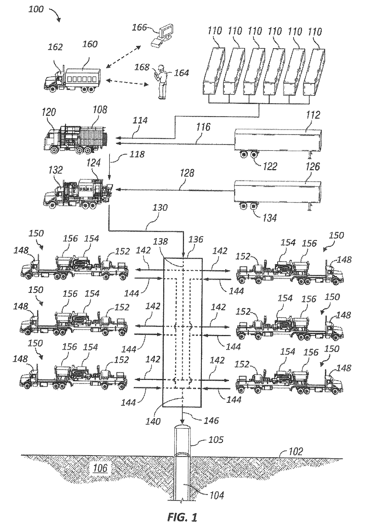
a wellsite and pumping technology, applied in the direction of electric programme control, borehole/well accessories, program control, etc., can solve the problems of reducing pumping flow rate and efficiency, inconsistent pump performance, and exposing the user to a potentially dangerous environment, so as to increase the probability of achieving the target, increase the probability, and reduce the probability

Active Publication Date: 2019-09-17
SCHLUMBERGER TECH CORP
View PDF17 Cites 130 Cited by
  • Summary
  • Abstract
  • Description
  • Claims
  • Application Information

AI Technical Summary

Benefits of technology

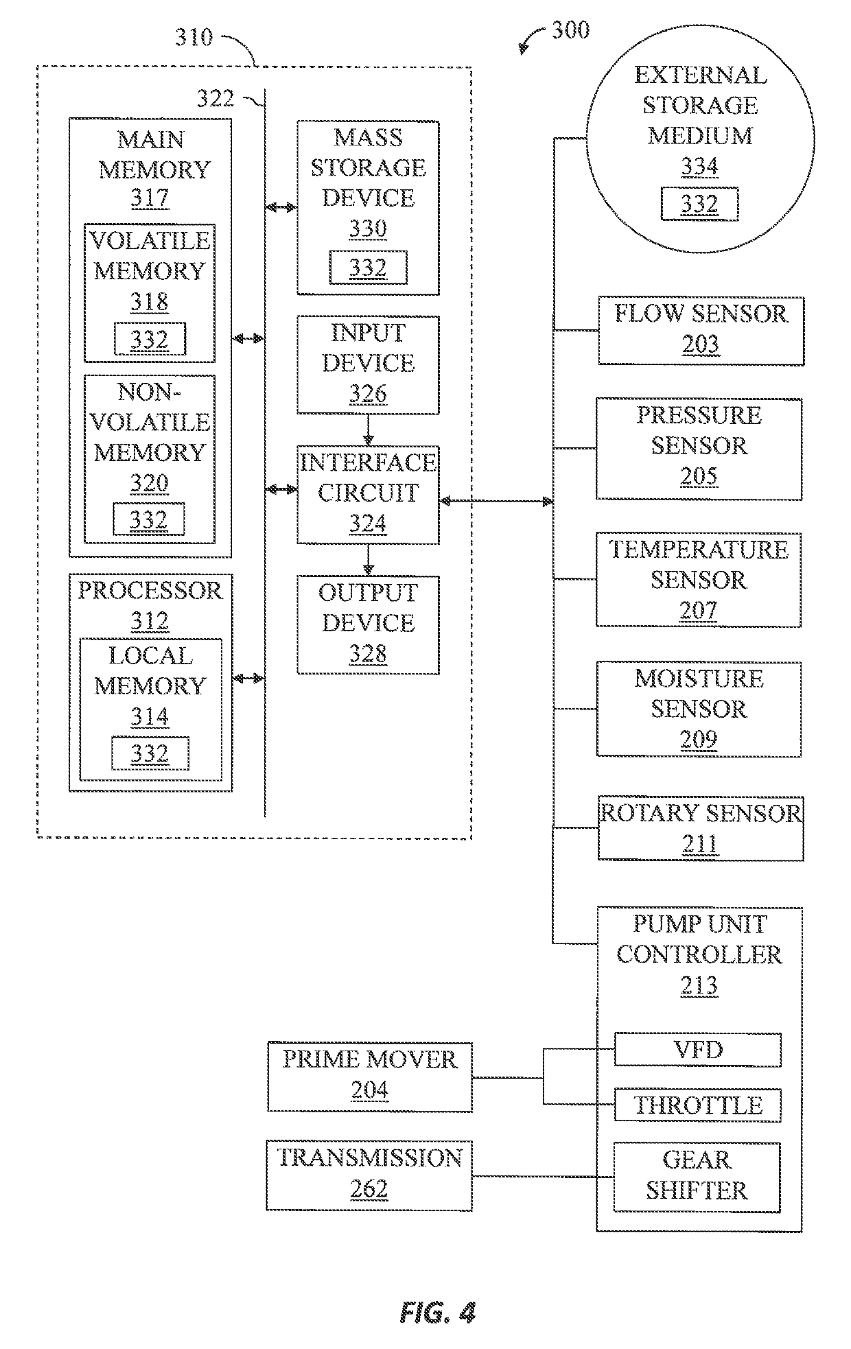
The patent describes a device and method for automatically controlling the flow rate of a pump. The controller uses a mathematical model to determine the relationship between the flow rate and the speed of the pump. Based on this model, the controller selects the target speed of the pump to achieve the desired flow rate and adjusts the pump speed to match the target. The controller also updates the model based on the actual flow rate and discharge pressure to improve the probability of achieving the target flow rate. The technical effects of the patent are improved efficiency and accuracy of pump flow control, reduced likelihood of blockages and leakages, and improved overall performance of the pump system.

Problems solved by technology

Systematic high fluid pressures, flow rates, and vibrations generated by the pumps may cause mechanical fatigue, wear, and other damage to the pumps, which may decrease pumping flow rates and efficiency.
To perform tests and to oversee the actual downhole pumping operations, the operators typically approach the pumps to visually inspect the fluid sensors and to manually adjust the pumps, thus exposing themselves to a potentially dangerous environment.
Approaching the pumps during testing or pumping operations may be dangerous, such as because high-pressure fluid within the pumps may escape, which may lead to serious injuries.
Also, performing the testing and pumping operations manually may result in inconsistent pump settings and, thus, inconsistent pump performance.
Furthermore, automated control of pumps using gear and throttle control is difficult, as the pumps may be constructed using different components and may have experienced different levels of wear and tear.
Therefore, a same “operation set-point” (i.e., gear and throttle set-point pair) may result in a different output flow rates for different pumps in addition, different wear levels of different pump components increase the variability in operating the pumps to achieve a target flow rate.
Automated monitoring of pump parameters is another challenge associated with pump operation.
External factors such as, but not limited to, pressure response from the well may invalidate previously made decisions and necessitate the operator to alter the engine speed (e.g., throttle) and transmission (i.e., gear) set-points to prevent damage to the pump unit, to achieve the intended rate in a different way, or to adjust the intended flow rate because it is no longer achievable.

Method used


Image

  • Automated operation of wellsite pumping equipment
  • Automated operation of wellsite pumping equipment
  • Automated operation of wellsite pumping equipment

Examples


Embodiment Construction

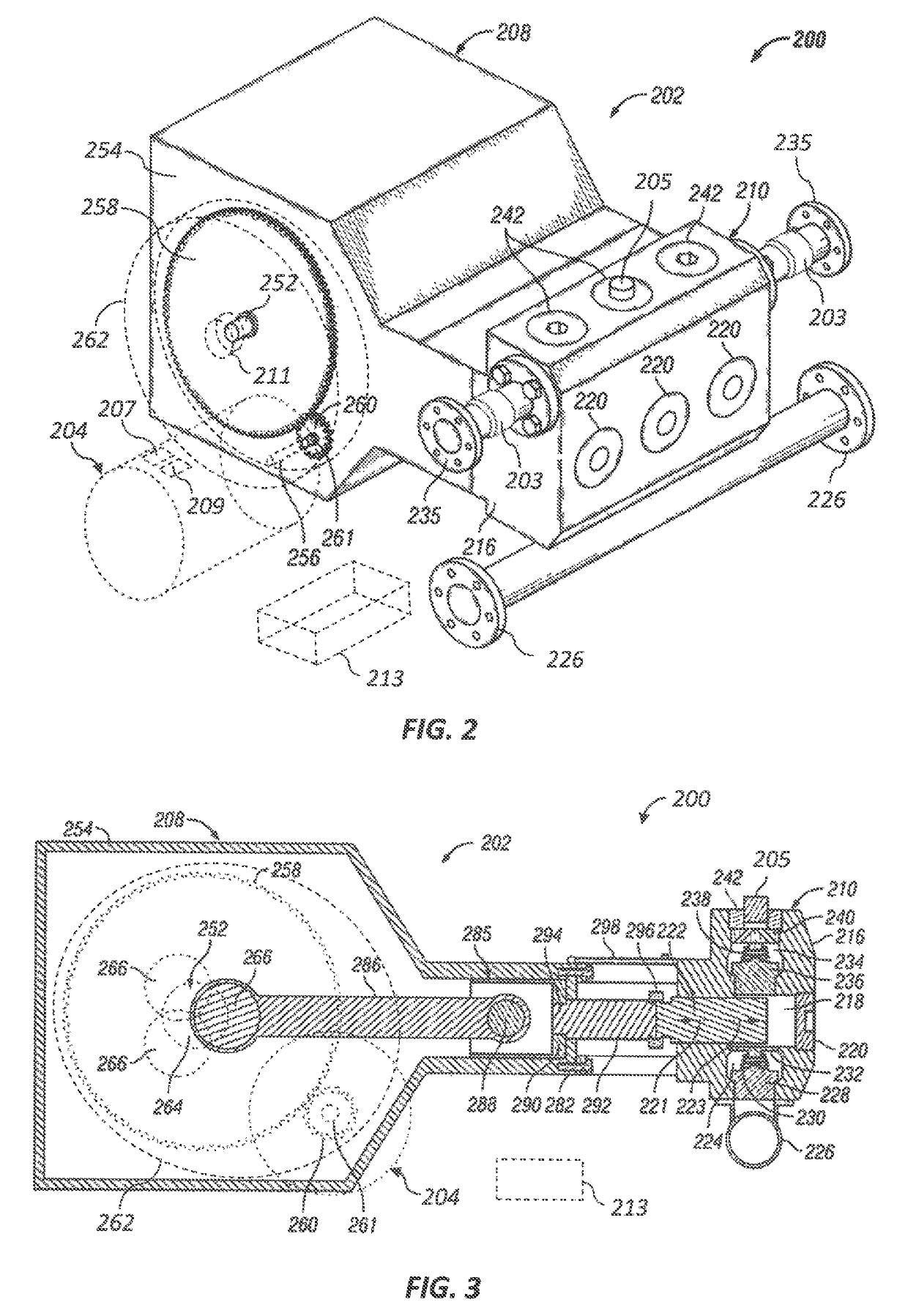
[0021]It is to be understood that the following disclosure provides many different embodiments, or examples, for implementing different features of various embodiments. Specific examples of components and arrangements are described below to simplify the present disclosure. These are, of course, merely examples and are not intended to be limiting. In addition, the present disclosure may repeat reference numerals and / or letters in the various examples. This repetition is for simplicity and clarity, and does not in itself dictate a relationship between the various embodiments and / or configurations discussed. Moreover, the formation of a first feature over or on a second feature in the description that follows may include embodiments in which the first and second features are formed in direct contact, and may also include embodiments in which additional features may be formed interposing the first and second features, such that the first and second features may not be in direct contact....


PUM


Abstract

Automated operation of well site pumping equipment, including generating a mathematical belief model for maintaining an interrelationship between flow rate achievable by a pump unit discharge pressure of the pump unit, and probability of achieving the flow rate at corresponding discharge pressure. Speed of the pump unit is controlled to achieve a target speed based on a flow rate set-point and the mathematical belief model and updating the mathematical belief model at least while the target speed is achieved. Updating the mathematical belief model may include increasing the probability of achieving the flow rate set-point when actual flow rate of the pump unit is not less than the flow rate set-point and decreasing the probability of achieving the flow rate set-point when the actual flow rate of the pump unit is less than the flow rate set-point.

Description

CROSS-REFERENCE TO RELATED APPLICATIONS[0001]This application claims priority to and the benefit of U.S. Provisional Application No. 62 / 269,947, titled “Adaptive, Learning-Based Approach for Pump Rate Control Automation,” filed Dec. 19, 2015, the entire disclosure of which is hereby incorporated herein by reference.BACKGROUND OF THE DISCLOSURE[0002]High-volume, high-pressure pumps are utilized at wellsites for a variety of pumping operations. Such operations may include drilling, cementing, acidizing, water jet cutting, hydraulic fracturing, and other wellsites operations. In some pumping operations, several pumps may be fluidly connected to a well via various fluid conduits and / or a manifold. During such operations, the fluid conduits and / or the manifold distributes low-pressure fluid from a mixer, a blender, and / or other sources among the pumps and combines pressurized fluid from the pumps for injection into the well.[0003]Success of the pumping operations at a wellsites may be af...

Claims


Application Information

Patent Timeline
Patent Type & Authority Patents(United States)
IPC IPC(8): F04B49/10G05B19/04G05B19/042E21B44/00F04B49/08F04B49/06F04B47/02F04B47/00E21B43/12
CPCG05B19/042G05B19/04F04B49/065E21B44/00F04B47/02F04B49/08F04B47/00F04B49/106E21B43/12F04B49/06G05B2219/41108E21B43/2607
Inventor KAJITA, MARCOSLOPEZ, MIGUEL ANGELJWAIR, HASSANAIN A.BOBADILLA LARIOS, MANUEL ALFONSOFAUGHT, EDWIN GUY
Owner SCHLUMBERGER TECH CORP
Learn More