Electronic device, electronic apparatus, and vehicle

a technology of electronic equipment and electronic components, applied in the direction of electrical equipment, impedence networks, semiconductor devices, etc., can solve problems such as damage generated, and achieve the effect of high reliability and excellent impact resistan

Active Publication Date: 2019-09-17
SEIKO EPSON CORP +1
View PDF26 Cites 0 Cited by
  • Summary
  • Abstract
  • Description
  • Claims
  • Application Information

AI Technical Summary

Benefits of technology

[0011]According to this application example, by satisfying the relationship of L1>L2, since the first projection portion and the second projection portion are disposed to partially overlap the vibration element on the free end portion side of the vibration element at two locations, it is possible to support the free end portion of the vibration element which is displaced as the impact is applied to the vibration element at two overlapped locations. Therefore, it is possible to further reduce damage of the vibration element generated as the free end portion of the vibration element is largely displaced due to the impact. In addition, by satisfying the relationship of L2>L3, since the first projection portion and the second projection portion do not overlap the electrode film which configures the excitation electrode, it is possible to reduce a concern about damage of the excitation electrode due to contact of the first projection portion and the second projection portion with the excitation electrode. Therefore, it is possible to reduce a change in the reference frequency or deterioration of the temporal change characteristics. Accordingly, there is an effect that an electronic device having excellent impact resistance and stable oscillation characteristics can be obtained.APPLICATION EXAMPLE 2
[0041]According to these application examples 18 and 19, a vehicle having excellent impact resistance and high reliability can be obtained by providing the electronic device of the present invention.

Problems solved by technology

Therefore, in a case where an impact caused by dropping is applied to the oscillator, there is a problem that there is a concern about damage generated as a free end portion of the vibration element is largely displaced and comes into contact with a part of the container.

Method used


Image

  • Electronic device, electronic apparatus, and vehicle
  • Electronic device, electronic apparatus, and vehicle
  • Electronic device, electronic apparatus, and vehicle

Examples


application example 2

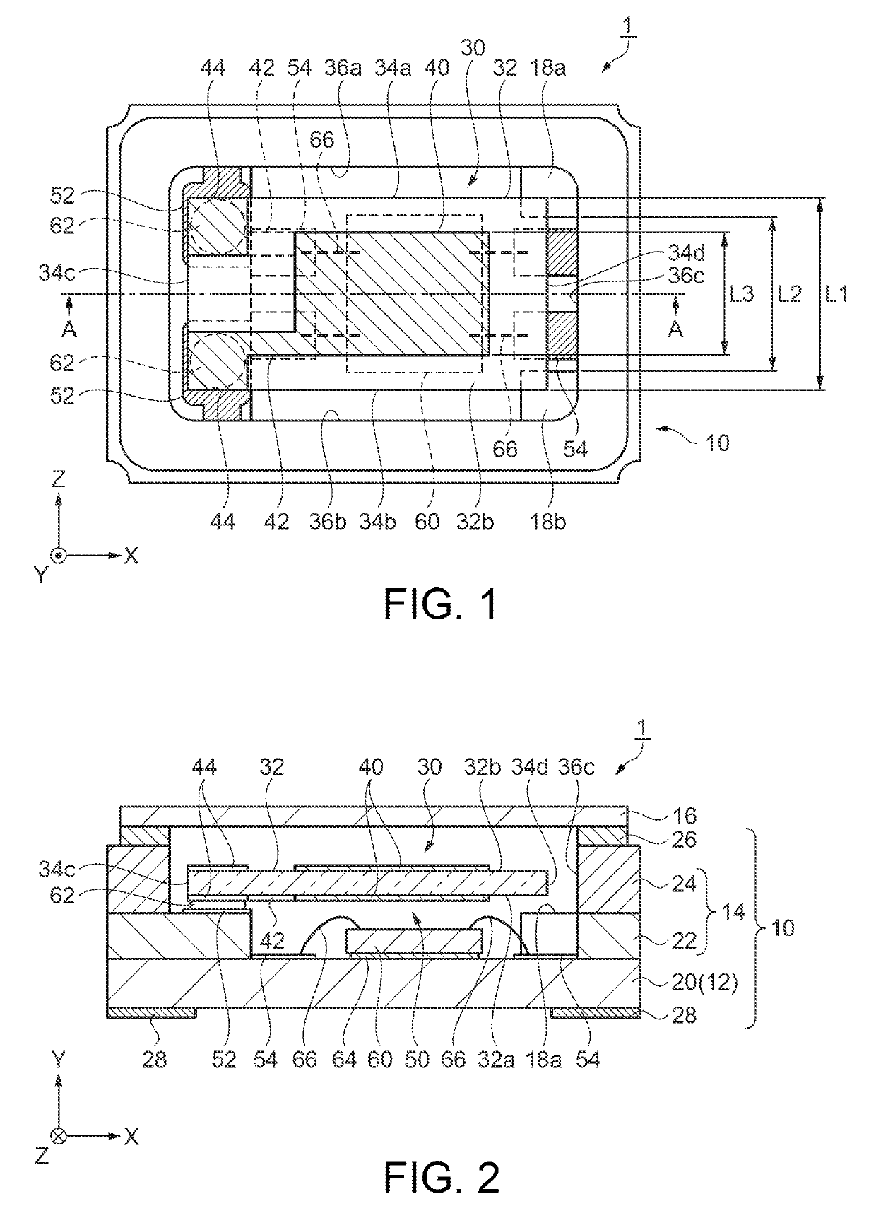
[0012]In the electronic device according to the above-described application example, the container includes a first side wall portion disposed in the direction along the first side surface, a second side wall portion disposed in the direction along the second side surface, and a third side wall portion disposed in the direction along the fourth side surface, in a plan view, the first projection portion is projected in the direction of the third side surface from a region in which the first side wall portion and the third side wall portion come into contact with each other, and the second projection portion is projected in the direction of the third side surface from a region in which the second side wall portion and the third side wall portion come into contact with each other.

[0013]According to this application example, since the first projection portion and the second projection portion are disposed toward the direction of the third side surface of the vibration element from the t...

application example 3

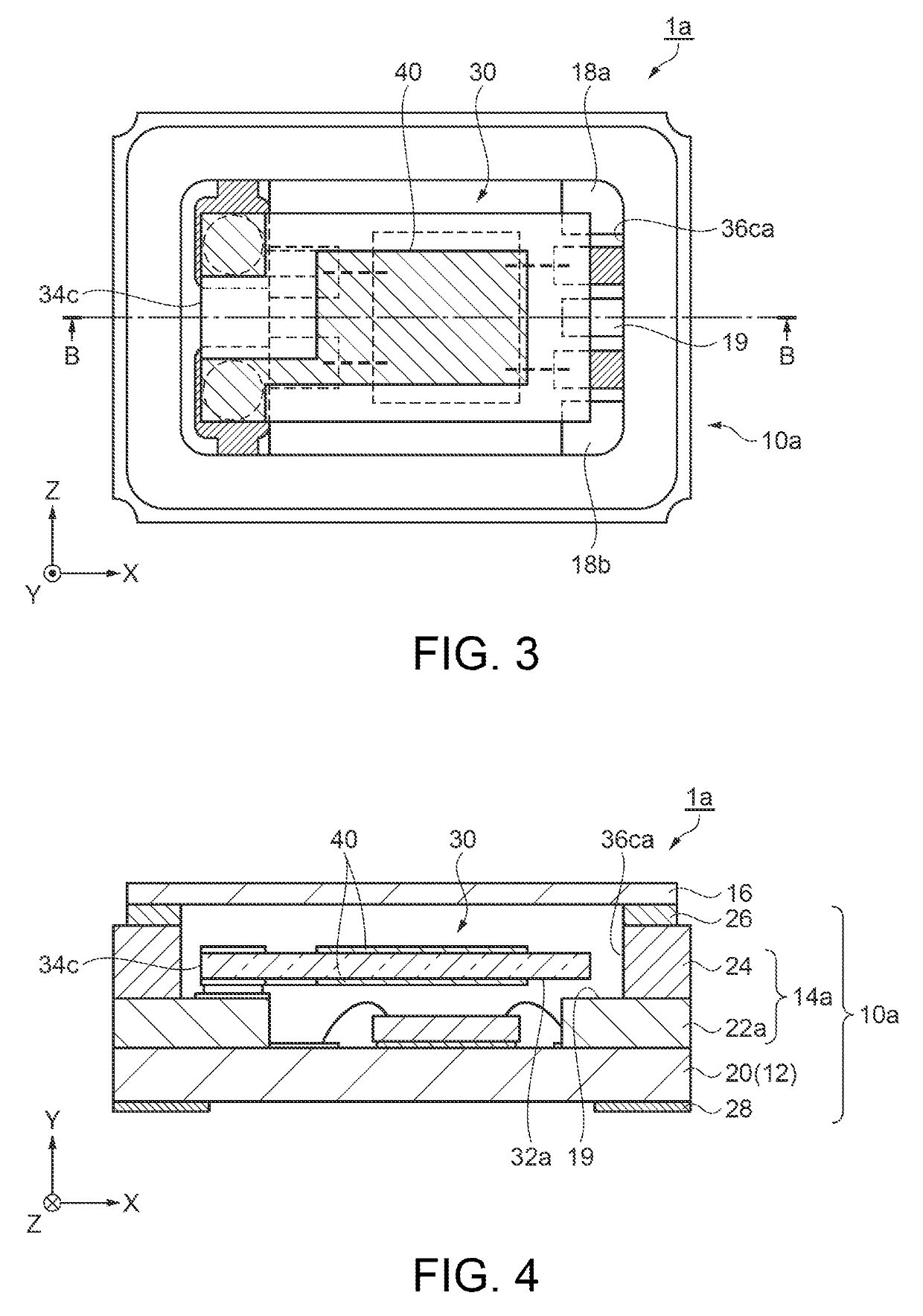
[0014]The electronic device according to the above-described application example, further includes: another projection portion disposed on the bottom plate, in which another projection portion partially overlaps the fourth side surface, and does not overlap the electrode film, in a plan view.

[0015]According to this application example, since the third projection portion which is another projection portion is disposed toward the direction of the third side surface from the third side wall portion in addition to the first projection portion and the second projection portion, it is possible to support the free end portion of the vibration element at three locations, and to further reduce a concern about damage of the vibration element generated as the free end portion of the vibration element is largely displaced due to the impact.

application example 4

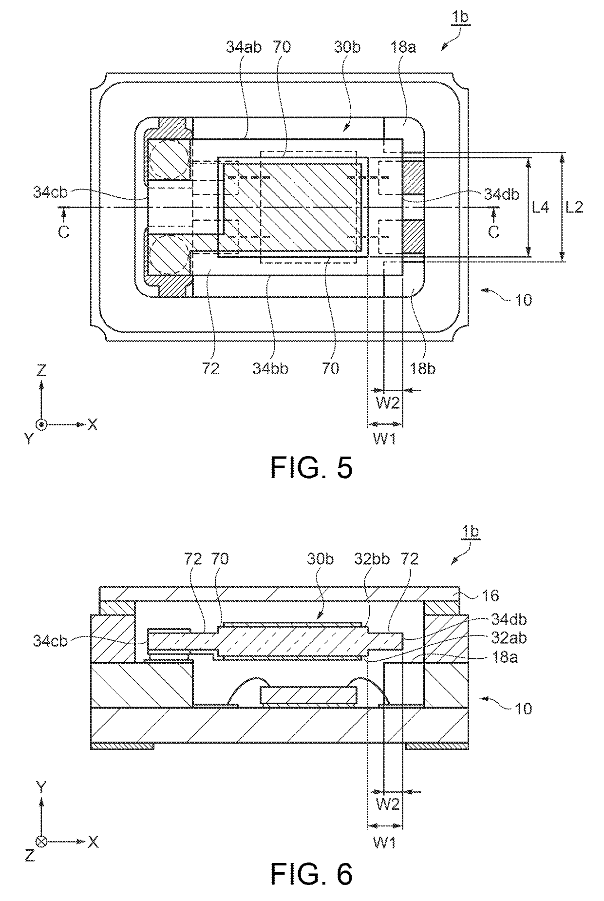
[0016]In the electronic device according to the above-described application example 1 or 2, the vibration element includes a first region having a first thickness along the vertical direction of the first surface, and a second region which is integrally provided in an outer circumference of the first region and has a second thickness which is thinner than that in the first region along the vertical direction, and a relationship of L2>L4 and W1>W2 is satisfied when an interval between the end portion on the first side surface side and the end portion on the second side surface side of the first region is L4, an interval between the end portion of the fourth side surface and the end portion on the fourth side surface side of the first region is W1, and a longer interval among the interval between the end portion of the fourth side surface and the end portion on the third side surface side of the first projection portion, and the interval between the end portion of the fourth side surf...


PUM


Abstract

An electronic device includes: a container including first and second projections disposed on a bottom plate; and a vibration element having an end on a third surface side of the vibration element placed in a container via a connector so that the first and second projections, and a first surface face each other with a void therebetween, and the first and second projection portions partially overlap the first surface on a fourth surface side of the vibration element, and are aligned along the direction intersecting the longitudinal direction of the vibration element. In addition, a relationship of L1>L2>L3 is satisfied when an interval between ends in the intersecting direction is L1, an interval between the first and second projections is L2, and an interval between ends in the intersecting direction of an electrode film is L3.

Description

TECHNICAL FIELD[0001]The present invention relates to an electronic device, an electronic apparatus provided with the electronic device, and a vehicle.BACKGROUND ART[0002]The electronic device which uses a piezoelectric material, such as quartz crystal, is used in many fields as an electronic component, such as an oscillator, a vibrator, a resonator, and a filter.[0003]Among these, the oscillator is widely used in electronic apparatuses as a timing source including a time source or a control signal, a reference signal or the like. In the oscillator, a vibration element which has excitation electrodes provided on opposing main surfaces of a vibration region of the vibration element, and an electronic component which excites the vibration element and generates a stable reference frequency, are loaded in a container having an accommodation space, and the oscillator is air-tightly sealed. The vibration element is loaded in a cantilever structure of which only one end side is fixed in or...

Claims


Application Information

Patent Timeline
Patent Type & Authority Patents(United States)
IPC IPC(8): H01L41/09H03H9/17H03H9/25H03H9/05H03B28/00H03H9/19H03H9/10
CPCH03H9/0547H03H9/1021H03H9/058H03B28/00H03H9/19H03H9/25H01L2224/73265H01L2924/00014H01L2224/48091
Inventor CHIBA, SEIICHI
Owner SEIKO EPSON CORP
Why Eureka
Try Eureka