Clutch driving device for deceleration clutch

a technology of clutches and driving devices, which is applied in the direction of clutches, other washing machines, textiles and papermaking, etc., can solve the problems of poor practicability, high noise, and low efficiency, and achieves simple control, high integration, and reduces the chance of the drive motor being damaged.

Active Publication Date: 2019-09-24
QINGDAO HAIER WASHING MASCH CO LTD
View PDF8 Cites 0 Cited by
  • Summary
  • Abstract
  • Description
  • Claims
  • Application Information

AI Technical Summary

Benefits of technology

[0059]The technical proposal of the disclosure brings the following beneficial effects:
[0060]1. The disclosure using the drive wheel to drive the shift fork which has the following characters: simple structure, simple operation, high reliability, smaller stroke, more compact structure, and less space occupied.
[0063]4. The drive motor is mounted on the deceleration clutch shell or the mounting plate which is mounted near the deceleration clutch shell, and the components are highly integrated. The drive motor is installed in the internal space of the mounting cover, which isolates the drive motor from the outside, prevents water droplets and water vapor from entering the drive motor, and reduces the chance of the drive motor being damaged by collision.
[0064]5. The disclosure can control the movement of the shift fork only by controlling the rotation of the drive wheel, the control is simple. The supporting slide rail can drive the two-way movement of the shift fork lever, and the reset spring can be canceled according to the design; the assembly process is simplified in the mass production and reduce the number of parts and costs.
[0065]6. The disclosure only controls the rotation of the drive wheel to realize the movement of the shift fork, the control is simple, the cam structure is simple and compact, and the design is convenient.
[0066]7. The disclosure can control the movement of the shift fork only by controlling the rotation of the drive wheel, the control is simple. The bracing rod can drive the two-way movement of the shift fork, and the reset spring can be canceled according to the design; the assembly process is simplified in the mass production and reduces the number of parts and costs.

Problems solved by technology

This kind of deceleration clutch has the characteristics of low efficiency, high noise, poor practicability, and high failure rate of the transmission part, so the technical proposal of the coaxial setting of the motor and clutch is put forward.
But the structure of the motor connection is complex, can only implement the ordinary washing method.
Since the deceleration clutch has many shortcomings such as: the main parts have too many connection components, the installation requirements are too high, high fault rate, so the deceleration clutch of the solution from the patent is not suitable for manufacture.
But the clutch control mechanism is complex and cumbersome to control.
However, the method of controlling the up-and-down movement of the clutch sleeve has a low accuracy rate, a high failure rate, a large occupied space, and a low component integration ratio.

Method used


Image

  • Clutch driving device for deceleration clutch
  • Clutch driving device for deceleration clutch
  • Clutch driving device for deceleration clutch

Examples


embodiment 1

[0087

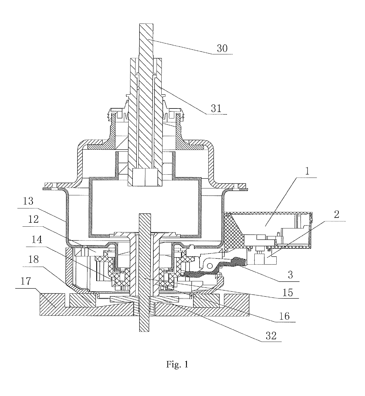
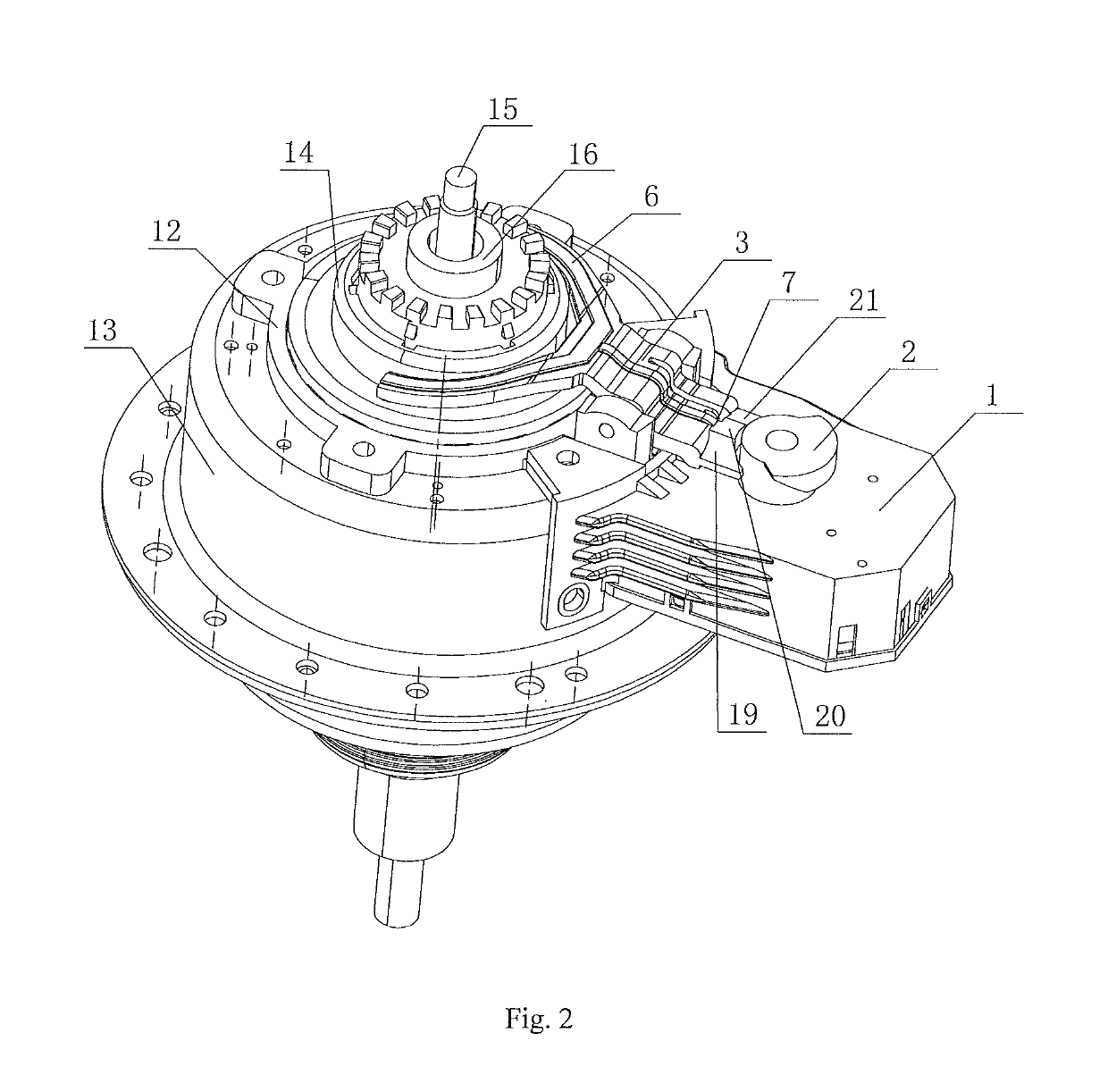
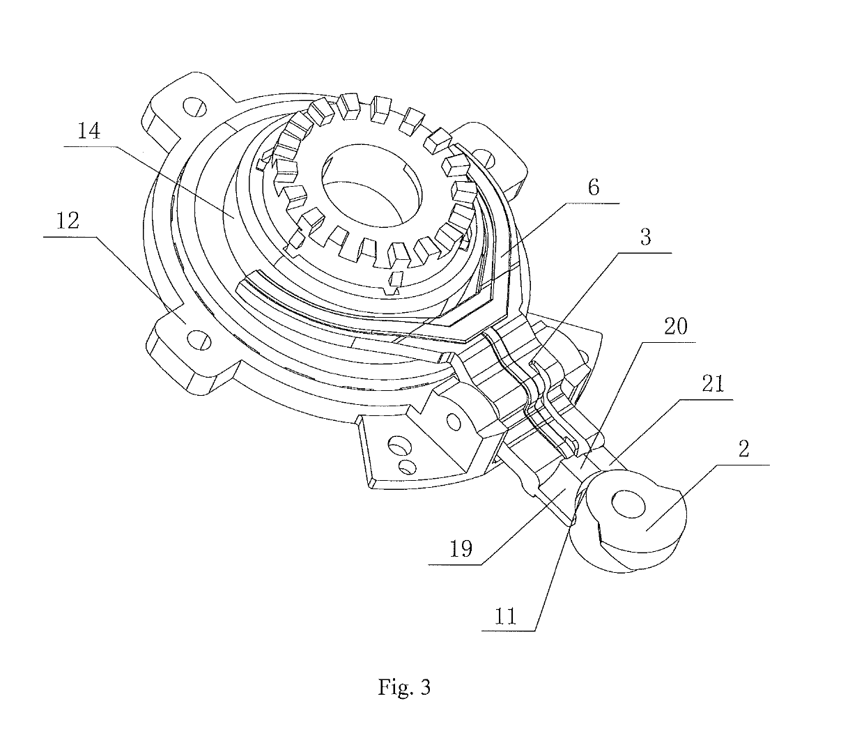
[0088]As shown in from FIG. 2 to FIG. 5, a clutch driving device for a deceleration clutch of the present embodiment comprises a drive motor 1, a drive wheel 2 and a shift fork lever 3. The drive wheel 2 is arranged on a motor shaft of the drive motor 1, supporting faces with a height difference in the axial direction are arranged on the circumference of the drive wheel 2. The shift fork lever 3 is a lever structure and a fixed fulcrum is set in the middle part; a head of the shift fork lever 3 is a shift fork 6. The shift fork 6 is located below a clutch sleeve 14, together with a return spring controls the vertical movement of the clutch sleeve 14. A tail of the shift fork lever 3 is a drive end 7, slide contacting surfaces are provided on the drive end 7 for sliding engagement with supporting surfaces. The drive motor 1 drives the drive wheel 2 to rotate, the drive end 7 of the shift fork lever relatively slides on the supporting surfaces, so that a height of the drive end 7...

embodiment 2

[0103

[0104]As shown in FIG. 6 and FIG. 7, a driving device for a deceleration clutch of the present embodiment comprises a drive motor 1, a drive wheel 2, a shift fork lever 3, the drive wheel 2 is directly mounted on a motor shaft of the drive motor 1, the drive wheel 2 axis is parallel to the axis of a clutch sleeve 14, the drive wheel 2 is provided with a supporting slide rail with a height difference in the axial direction. The shift fork lever 3 is a lever structure and a fixed fulcrum is set in the middle part, a head portion of the shift fork lever 3 is a shift fork 6, the shift fork 6 is below the clutch sleeve 14. The shift fork lever together with a return spring controls the up and down movement of the clutch sleeve 14. The tail portion of the shift fork lever 3 is a drive end 7, the drive end 7 is provided with a slide contacting surface which is supported in the supporting slide rail. The drive motor drives the drive wheel to rotate, the slide contacting surface of the ...

embodiment 3

[0117

[0118]As shown in FIG. 8 and FIG. 9, a driving device for a deceleration clutch of the present embodiment comprises a drive motor 1, a drive wheel 2, and a shift fork lever 3. The shift fork lever 3 is a lever structure and a fixed fulcrum is set in the middle part. A head of the shift fork lever 3 is a shift fork 6. The shift fork 6 is located below a clutch sleeve 14 together with a return spring to control the vertical movement of the clutch sleeve 14. A tail of the shift fork lever is a drive end 7 which is connected with the drive wheel 2. An axis of the drive wheel is perpendicular to an axis of a clutch sleeve. The drive wheel is a cam structure, and the cam circumference is radially gradient. The tail portion of the shift fork lever is supported on a cam circumferential surface, the drive motor drives the cam to rotate. The tail portion of the shift fork lever is in contact with the circumference of different radius of the cam, a height changes, which drives a height of...


PUM


Abstract

A driving device for a deceleration clutch, comprises a on a driving motor shaft. The drive wheel has a supporting surface with a height difference in the axial direction. A head of a shift fork lever controls the clutch sleeve to move up and down. A tail of the shift fork lever is supported on the supporting surface. The tail of the shift fork lever relatively slides on the supporting surface, so that a height of the tail of the shift fork lever changes which drives a height of the head of the shift fork and further drives the clutch sleeve to move up and down. Alternatively, the drive wheel has a supporting slide rail with a height difference in the axial direction, or has cam circumference that is radially gradient, or a bracing rod is eccentrically arranged on an end surface of the drive wheel.

Description

FIELD OF THE INVENTION[0001]The present disclosure relates to the field of washing machine, and more particularly, to a clutch driving device for deceleration clutch.BACKGROUND OF THE INVENTION[0002]The existing technology, such as a washing machine on the market provided with a deceleration clutch which is parallel installed with a single-phase asynchronous motor and driven by the pulley and belt. This kind of deceleration clutch has the characteristics of low efficiency, high noise, poor practicability, and high failure rate of the transmission part, so the technical proposal of the coaxial setting of the motor and clutch is put forward. So the relevant technical personnel put forward the technical solution for setting motor and clutch coaxial. Such as a patent with patent number ZL00234747.4 discloses a deceleration clutch of a washing machine directly driven by brushless motor. The patent uses a brushless motor directly driving the washing machine clutch, solves the problem that...

Claims


Application Information

Patent Timeline
Patent Type & Authority Patents(United States)
IPC IPC(8): F16D23/12D06F37/30D06F37/40F16D11/14F16D28/00F16D23/14
CPCF16D28/00D06F37/40D06F37/30F16D11/14F16D23/12F16D2023/141F16D2023/123
Inventor LV, PEISHIZHANG, GANGJINTIAN, YUN
Owner QINGDAO HAIER WASHING MASCH CO LTD
Why Eureka
Try Eureka