
Process corner detection circuit based on self-timing oscillation ring

a detection circuit and self-timing technology, applied in pulse generators, instruments, pulse techniques, etc., can solve the problems of increasing the difficulty of ensuring timing safety, increasing the fluctuation of parameters related to a design, and slowing down the device speed by process variation, etc., to achieve simple circuit structure, reduce the difficulty of design, and improve the effect of timing safety

Active Publication Date: 2019-09-24
SOUTHEAST UNIV
View PDF10 Cites 0 Cited by
  • Summary
  • Abstract
  • Description
  • Claims
  • Application Information

AI Technical Summary

Benefits of technology

The circuit accurately detects process corners, reducing the impact of process variations and improving chip stability by distinguishing between different process corners without overlapping results due to temperature fluctuations, and includes a reset mechanism for efficient power management.

Problems solved by technology

However, with manufacturing processes continuously advancing toward nano scale, the effect of variations of factors such as process, voltage, temperature (Process-Voltage-Temperature, PVT) on an integrated circuit timing gets larger and larger, and guaranteeing the timing safety becomes increasingly difficult and costly, thus making it an important research subject.
In all of the factors affecting the chip timing, process variation is one of the main causes of timing fluctuation.
It was said in International Technology Roadmap for Semiconductors (ITRS), 2011, that: Since the feature size is reduced, one of key problems faced by designers is that fluctuation of parameters related to a design is continuously increasing, because manufacturing parameters variations and the inherent characteristic of the atom affect channel doping.
However, for a slowest process corner (Slow Corner), device speeds are slowed down by the process variation.
Although the effect of voltage fluctuations can be eliminated by using LDO supplying power to the circuit with stable and accurate voltage, the effect of temperature fluctuations on the ring oscillator cannot be eliminated.

Method used


Image

  • Process corner detection circuit based on self-timing oscillation ring
  • Process corner detection circuit based on self-timing oscillation ring
  • Process corner detection circuit based on self-timing oscillation ring

Examples


embodiment 1

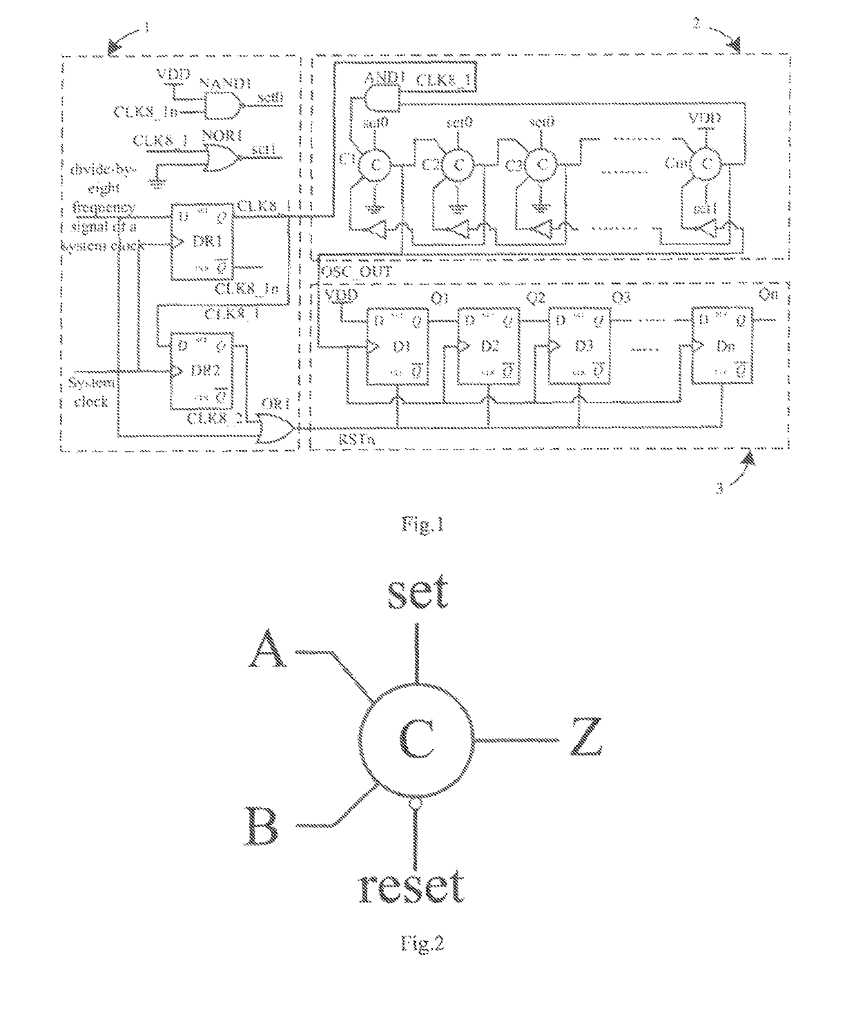
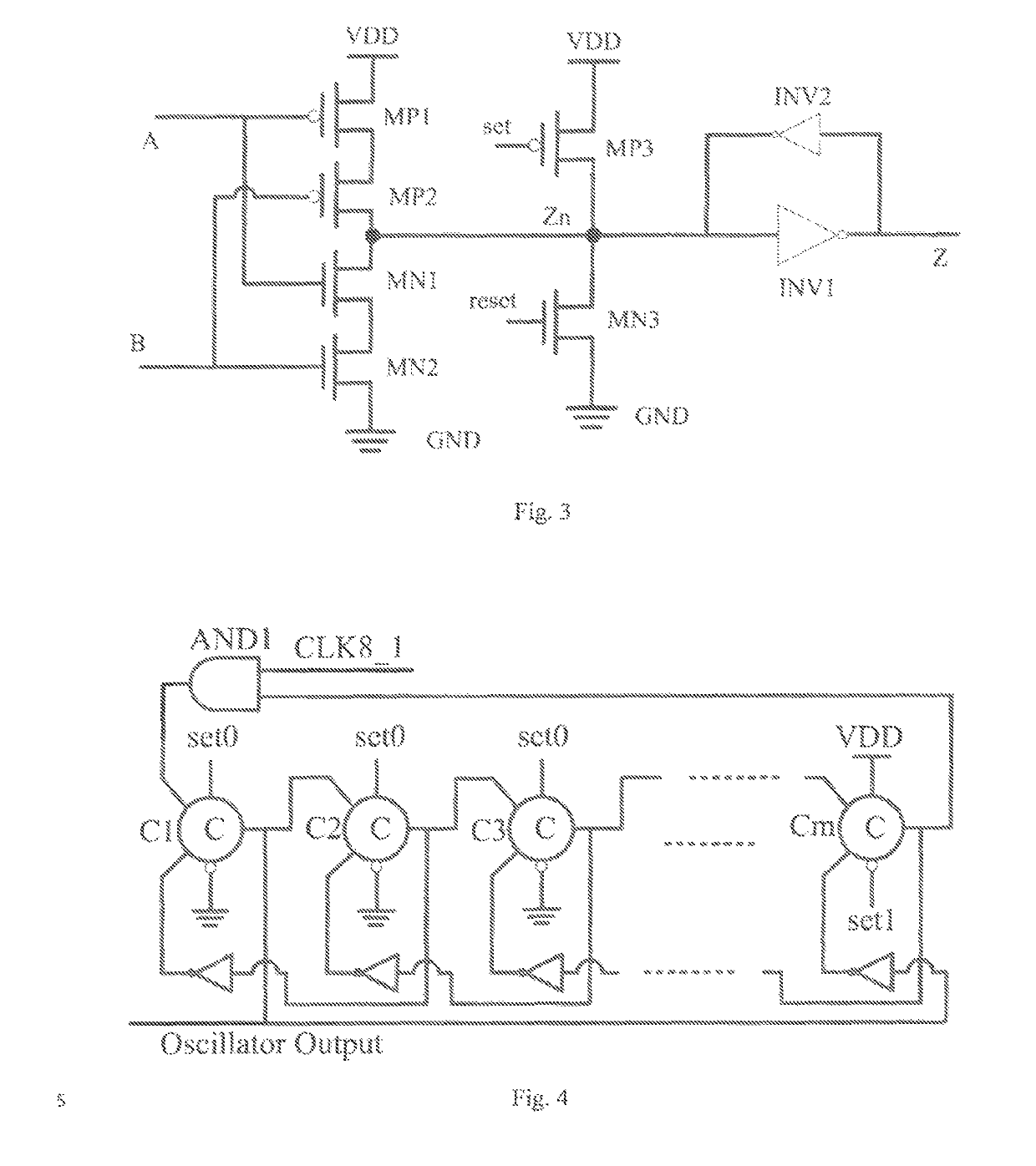
[0029]As shown in FIG. 1, the process corner detection circuit based on a self-timing ring oscillator of the present invention comprises a reset circuit, a self-timing ring oscillator, and a counting module. The self-timing ring oscillator comprises at least three stages of Muller C-elements and inverters, and the counting module comprises at least three flip-flops. In different process corners, the numbers of the oscillations of the self-timing ring oscillator within the same period are different, and the number of the flip-flops in the counting module should be larger than the largest number of the oscillations of the self-timing ring oscillator during an oscillation period. When the stage of the Muller C-element and the inverter included in the self-timing ring oscillator is 9, and the stage of the flip-flop included in the counting module is 32, a detailed implementation is as follows:

[0030]As shown in FIG. 1, the reset circuit is constituted by two flip-flops DR1 and DR2, a two...


PUM


Abstract

A process corner detection circuit based on a self-timing ring oscillator comprises a reset circuit (1), the self-timing oscillation ring (2), and a counting module (3). The self-timing ring oscillator (2) consists of m two-input Muller C-elements and inverters, and a two-input AND gate, m being a positive integer greater than or equal to 3. The circuit can be used for detecting a process corner of a fabricated integrated circuit chip, and reflecting the process corner of the chip according to the number of oscillations of the self-timing ring oscillator (2). The number of oscillations of the self-timing ring oscillator (2) in different process corners is acquired by Hspice simulation before the chip tape-out, and the process corner of the chip after the chip tape-out can be determined according to the actually measured number of oscillations.

Description

CROSS-REFERENCE TO RELATED APPLICATIONS[0001]This application is the National Stage of International Application No. PCT / CN2014 / 095074, filed on 26 Dec. 2014 claiming the priority of CN 201410291341.9 filed on 25 Jun. 2014, the content of each of which is incorporated by reference herein.TECHNICAL FIELD[0002]The present invention relates to a process corner detection circuit based on a self-timing ring oscillator, in which all circuit elements can be constituted by MOS transistors, and which is used for detecting the process corner of a fabricated integrated circuit chip, and belongs to the field of integrated circuit designs.BACKGROUND[0003]Guaranteeing that time delay changes of a timing path in a “timing safety” circuit of a circuit does not cause synchronization failure is one of the basic conditions for ensuring the circuit to work reliably. However, with manufacturing processes continuously advancing toward nano scale, the effect of variations of factors such as process, volta...

Claims


Application Information

Patent Timeline
Patent Type & Authority Patents(United States)
IPC IPC(8): G01R31/28H03K3/03
CPCG01R31/2837G01R31/2882H03K3/0315
Inventor SHAN, WEIWEISHI, LONGXINGYANG, JUN
Owner SOUTHEAST UNIV
Learn More