Image capturing lens assembly, imaging apparatus and electronic device

a technology of image capturing and lens assembly, applied in the field of image capturing lens assembly and imaging apparatus, can solve the problems of hard to reduce the size of products and difficult to keep a balance among lens elements

Active Publication Date: 2019-09-24
LARGAN PRECISION
View PDF7 Cites 4 Cited by
  • Summary
  • Abstract
  • Description
  • Claims
  • Application Information

AI Technical Summary

Benefits of technology

[0049]When a focal length of the focus tunable component is ft, and a focal length of the imaging lens system is fi, the following condition is satisfied: |fi|<|ft|. Therefore, it is favorable for reducing the sensitivity of the image capturing lens assembly and obtaining the effects of auto-focus and compactness by adjusting the focal length of the focus tunable component and the focal length of the imaging lens system so as to apply to wider electronic devices.
[0051]When an f-number of the image capturing lens assembly is Fno, the following condition is satisfied: 1.20<Fno<2.60. Therefore, the illuminance of the image surface can be enhanced by controlling the amount of incident light, thus it is favorable for the imaging apparatus including the image capturing lens assembly to obtain sufficient information under situations such as insufficient external light source (i.e. nighttime), or under short exposure time (i.e. dynamic photographing) etc., so that an electronic device including the imaging apparatus can obtain the image with certain quality after calculate by the processor so as to increase the using opportunity thereof. Preferably, the following condition can be satisfied: 1.30<Fno<2.0.
[0004]With the wider application of photographing modules, specifications of lens assemblies in response to market demands are becoming diverse and strict. The size of products is hard to reduce due to the restrictions of shapes and materials of lens elements in conventional photographing modules, and it is also hard to keep a balance among molding of lens elements, assembling convenience and system sensitivity. Moreover, a lens assembly with auto-focus ability can adjust the focal length thereof depending on the imaged object location, and therefore obtain clear image on an image surface as well as increase resolution of the image and optimize the image quality. Hence, one lens assembly featuring compactness, easily assembling property and high image quality will fully satisfy market specifications and demands. The lens assembly can be applied to various kinds of electronic devices, such as intelligent electronic devices, multiple lens devices, wearable devices, digital cameras, image recognition systems, entertainment systems, mobile devices, sporting cameras and intelligent home assisting systems.

Problems solved by technology

The size of products is hard to reduce due to the restrictions of shapes and materials of lens elements in conventional photographing modules, and it is also hard to keep a balance among molding of lens elements, assembling convenience and system sensitivity.

Method used


Image

  • Image capturing lens assembly, imaging apparatus and electronic device
  • Image capturing lens assembly, imaging apparatus and electronic device
  • Image capturing lens assembly, imaging apparatus and electronic device

Examples


1st embodiment

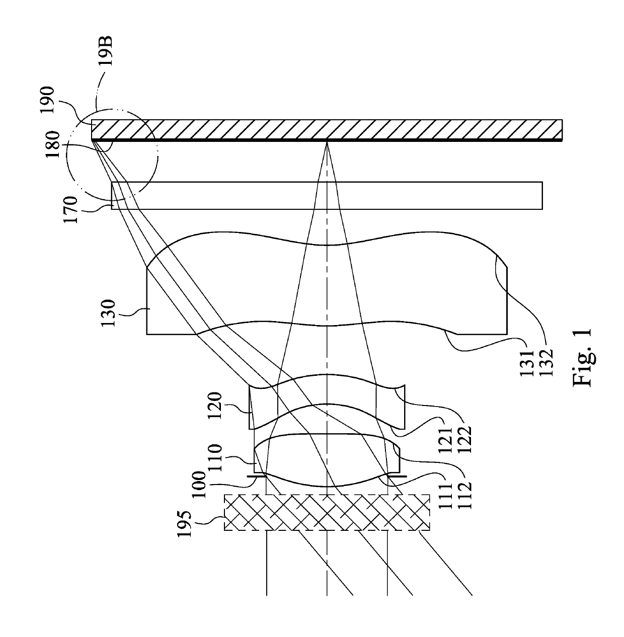
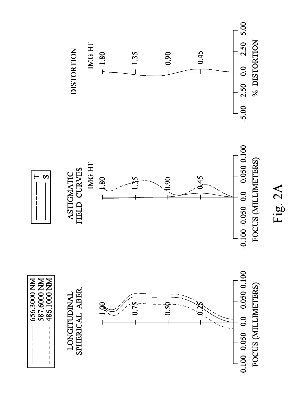
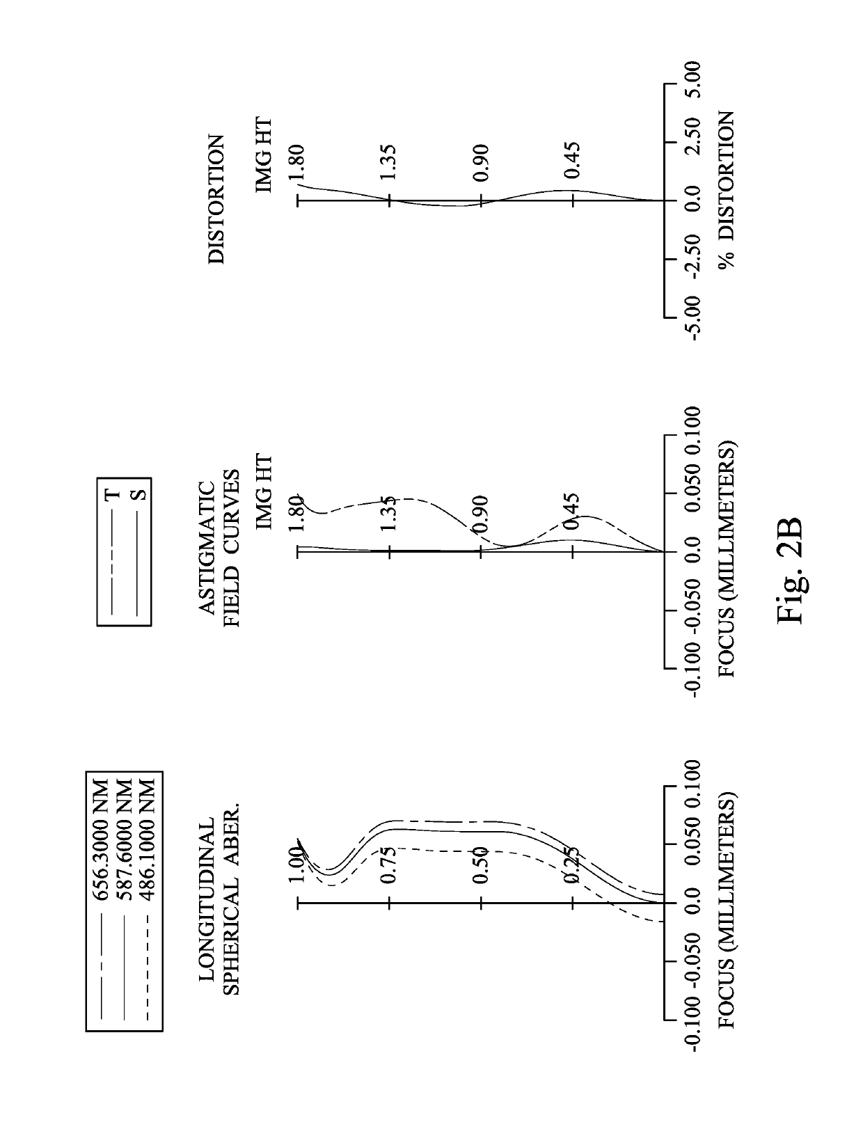
[0088]FIG. 1 is a schematic view of an imaging apparatus according to the 1st embodiment of the present disclosure. FIG. 2A shows spherical aberration curves, astigmatic field curves and a distortion curve of Mode 1 of the imaging apparatus according to the 1st embodiment, and FIG. 2B shows spherical aberration curves, astigmatic field curves and a distortion curve of Mode 2 of the imaging apparatus according to the 1st embodiment, wherein Mode 1 and Mode 2 are two modes of the imaging apparatus at two different focusing conditions, and the detailed conditions are shown in Table 1C below. In FIG. 1, the imaging apparatus includes an image capturing lens assembly (its reference numeral is omitted) and an image sensor 190. The image capturing lens assembly includes, in order from an object side to an image side, a focus tunable component 195, an aperture stop 100, a first lens element 110, a second lens element 120, a third lens element 130, a filter 170 and an image surface 180, and ...

2nd embodiment

[0111]FIG. 3 is a schematic view of an imaging apparatus according to the 2nd embodiment of the present disclosure. FIG. 4A shows spherical aberration curves, astigmatic field curves and a distortion curve of Mode 1 of the imaging apparatus according to the 2nd embodiment, and FIG. 4B shows spherical aberration curves, astigmatic field curves and a distortion curve of Mode 2 of the imaging apparatus according to the 2nd embodiment, wherein Mode 1 and Mode 2 are two modes of the imaging apparatus at two different focusing conditions, and the detailed conditions are shown in Table 2C below. In FIG. 3, the imaging apparatus includes an image capturing lens assembly (its reference numeral is omitted) and an image sensor 290. The image capturing lens assembly includes, in order from an object side to an image side, a focus tunable component 295, an aperture stop 200, a first lens element 210, a second lens element 220, a third lens element 230, a fourth lens element 240, a filter 270 and...

3rd embodiment

[0125]FIG. 5 is a schematic view of an imaging apparatus according to the 3rd embodiment of the present disclosure. FIG. 6A shows spherical aberration curves, astigmatic field curves and a distortion curve of Mode 1 of the imaging apparatus according to the 3rd embodiment, and FIG. 6B shows spherical aberration curves, astigmatic field curves and a distortion curve of Mode 2 of the imaging apparatus according to the 3rd embodiment, wherein Mode 1 and Mode 2 are two modes of the imaging apparatus at two different focusing conditions, and the detailed conditions are shown in Table 3C below. In FIG. 5, the imaging apparatus includes an image capturing lens assembly (its reference numeral is omitted) and an image sensor 390. The image capturing lens assembly includes, in order from an object side to an image side, a focus tunable component 395, an aperture stop 300, a first lens element 310, a second lens element 320, a third lens element 330, a fourth lens element 340, a fifth lens ele...


PUM

PropertyMeasurementUnit
Abbe numberaaaaaaaaaa
axial distanceaaaaaaaaaa
incident angleaaaaaaaaaa

Abstract

An image capturing lens assembly includes a focus tunable component and an imaging lens system. The imaging lens system includes a plurality of lens elements, wherein each of the lens elements has an object-side surface facing towards an object side of the imaging lens system and an image-side surface facing towards an image side of the imaging lens system, and at least one surface of at least one of the lens elements includes at least one inflection point.

Description

RELATED APPLICATIONS[0001]This application claims priority to U.S. Provisional Application Ser. No. 62 / 475,917, filed Mar. 24, 2017, which is herein incorporated by reference.BACKGROUNDTechnical Field[0002]The present disclosure relates to an image capturing lens assembly and an imaging apparatus. More particularly, the present disclosure relates to an image capturing lens assembly and an imaging apparatus with compactness applicable to electronic devices.[0003]Description of Related Art[0004]With the wider application of photographing modules, specifications of lens assemblies in response to market demands are becoming diverse and strict. The size of products is hard to reduce due to the restrictions of shapes and materials of lens elements in conventional photographing modules, and it is also hard to keep a balance among molding of lens elements, assembling convenience and system sensitivity. Moreover, a lens assembly with auto-focus ability can adjust the focal length thereof dep...

Claims


Application Information

Patent Timeline
Patent Type & Authority Patents(United States)
IPC IPC(8): G02B3/14G02B13/18G02B15/00G02F1/29G02B13/00
CPCG02B3/14G02B13/004G02B15/00G02B13/0045G02F1/29G02B13/0035G02B13/18G02F2001/294G02B13/002G02F1/294
Inventor HSIEH, TUNG-YIYANG, SHU-YUNTSENG, YU-TAI
Owner LARGAN PRECISION
Why Eureka
Try Eureka