Radiation detector

a technology of radiation detectors and detectors, applied in the direction of instruments, specific gravity measurement, machines/engines, etc., can solve the problems that the material used to form such panels may not be able to maintain a vacuum at high temperatures, and achieve the effect of safe use in explosive atmospheres and the most efficient removal of heat from detectors

Active Publication Date: 2019-10-29
JOHNSON MATTHEY PLC
View PDF29 Cites 1 Cited by
  • Summary
  • Abstract
  • Description
  • Claims
  • Application Information

AI Technical Summary

Benefits of technology

[0021]An intrinsically safe circuit is a circuit in which any spark or any thermal effect produced in the conditions specified in the standard, which include normal operation and specified fault conditions, is not capable of causing ignition of a given explosive atmosphere. An intrinsically safe electrical device is a device in which all of the electrical circuits are intrinsically safe circuits. The design and selection of components and the test criteria applied to such equipment is governed by national and international standards such as BS EN 60079-11:2012 and its related parts, including part 0 concerning general requirements for electrical equipment intended for use in explosive atmospheres. Preferably the detector probe conforms at least to Level of Protection ib of the standard, i.e. it is designed to be safe in use in explosive atmospheres in normal operation and with the application of those non-countable faults which give the most onerous condition; and in normal operation and with the application of one countable fault plus the application of those non-countable faults which give the most onerous condition as defined in section 5.3 of BS EN 60079-11:2012. Countable faults and non-countable faults are defined in BS EN 60079-11:2012 at paragraph 3.7. Most preferably, the detector probe conforms to Level of Protection is of the standard, i.e. it is designed to be safe in use in explosive atmospheres when the circuit contains two countable faults as defined in section 5.2 of BS EN 60079-11:2012. Such protection is achieved by the use of various components and construction methods which include, for example, the separation of parts of the circuits by minimum separation distances as set out in section 6.3 “Separation Distances” of BS EN 60079-11:2012.
[0022]The heat pipe may operate to remove heat from the space surrounding the detectors and this arrangement may be adequate in some versions of the invention. In a preferred embodiment of the invention, the detectors are mounted in direct thermal contact with the heat pipe. In this embodiment, the detectors may be physically supported on the heat pipe, for example using means such as adhesive, a strap, clip, cable-tie or other connector. When the detectors are mounted in thermal contact with the heat pipe, heat can be removed from the detectors most efficiently. In this embodiment, the detectors are preferably electrically isolated from the heat pipe by means of a material which is both thermally conductive and electrically insulating. Such materials include grease, mica and composite materials such as the commercially available Sil-Pad™ range of materials supplied by the Bergquist company.

Problems solved by technology

We have, however, found that the materials used to form such panels may not be capable of maintaining a vacuum at high temperatures.

Method used


Image

  • Radiation detector
  • Radiation detector
  • Radiation detector

Examples


Embodiment Construction

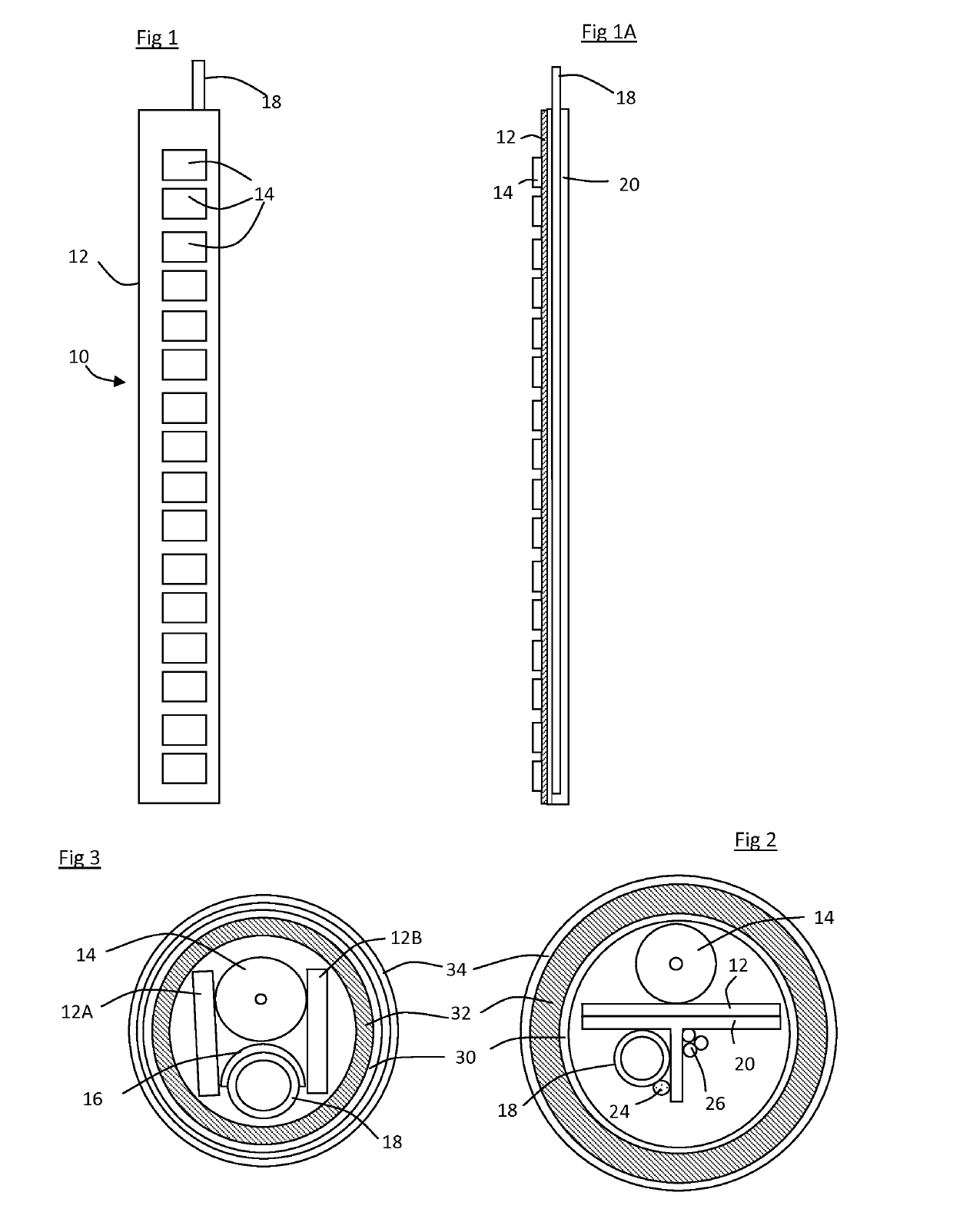
[0043]A sectional view of an alternative embodiment of the invention is shown in FIG. 3. In this embodiment, GM tube 14 is supported on the heat pipe 18. Pad 16 is formed from Sil-Pad™ 1500ST thermally conductive elastomer to provide thermal contact between the GM tube and the heat pipe and also electrical insulation between them. Printed circuit boards 12A and 12B are mounted on either side of and electrically connected to the GM tube, and transport power, control signals and measurement signals between the GM tube and the power source, electrical control and signal processing apparatus housed within a separate housing. The high voltage supply circuit to power the GM tubes is carried on circuit board 12A, whilst the electrical components of the driving circuit are housed on board 12B. In this embodiment, insulation 32 is located between a protective plastic cover 30 and the components of the detector probe.

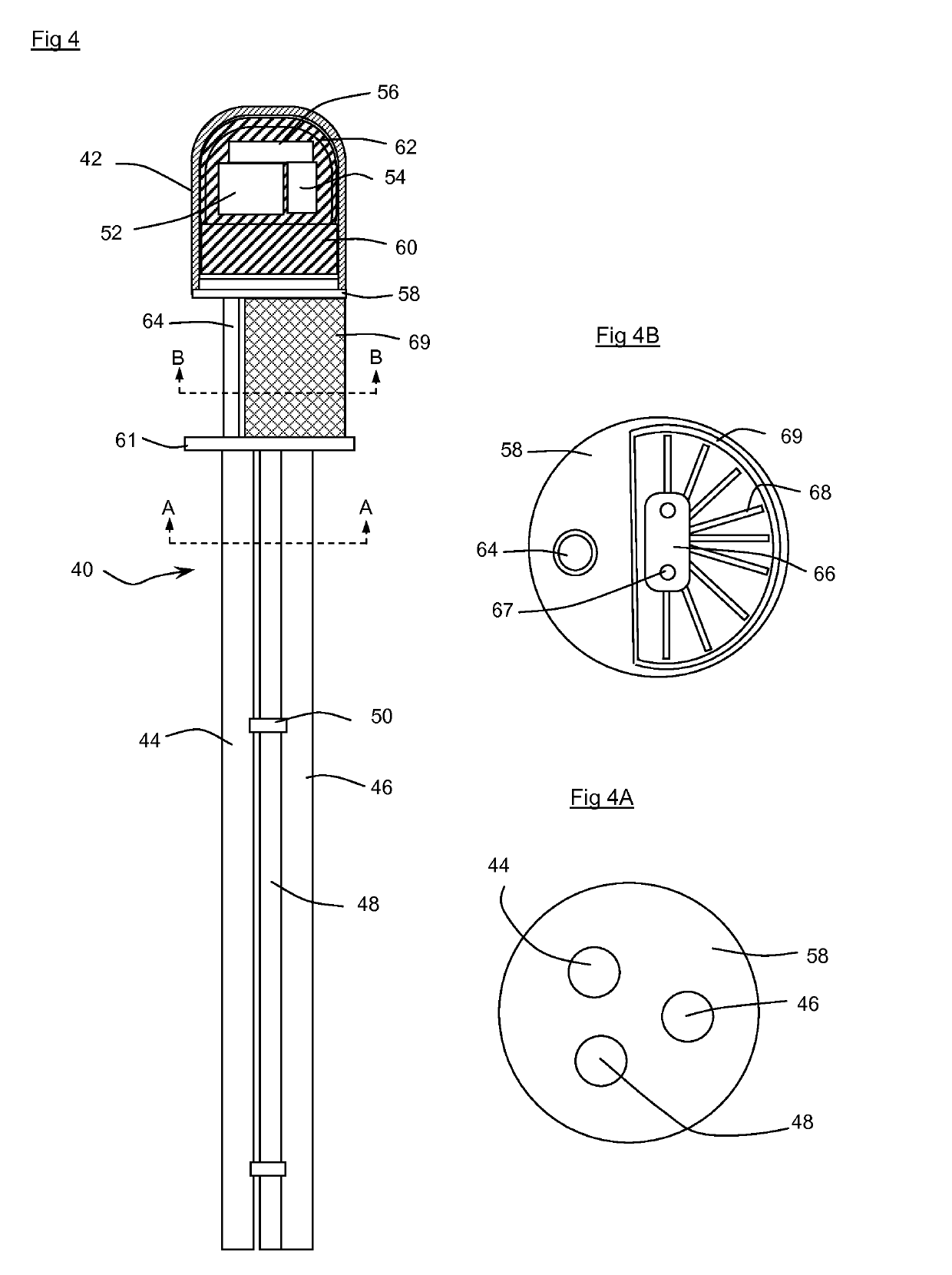
[0044]FIG. 4 shows an elevation of a density profiler instrument 40 accordin...


PUM

PropertyMeasurementUnit
freezing pointaaaaaaaaaa

Abstract

A detector probe, for detecting ionizing radiation and which is suitable for use in a nucleonic instrument usable in locations having a high ambient temperature, includes an array of radiation detectors mounted on a support and a heat pipe for cooling the detector probe. The nucleonic instrument incorporating such a detector probe is also described.

Description

BACKGROUND OF THE INVENTIONField of the Invention[0001]The present invention relates to an apparatus for measuring levels of materials, especially of fluids, and optionally for calculating a density profile of a mixed fluid system.Description of the Related Art[0002]A density profiler has been described in WO2000 / 022387. The device comprises a linear array of sources of ionising radiation which emit radiation towards detectors disposed in one or more linear arrays. When the source array and detector array(s) are positioned so that they traverse the interfaces between two or more fluids in a container, the interfaces of the fluids may be identified from the differences in radiation received by each detector in the array. The device has been successfully deployed for use in storage tanks and oil separators. In some circumstances it is required to operate density profilers in hot locations or where there is a risk that the instrument will be subjected to very high temperatures at certa...

Claims


Application Information

Patent Timeline
Patent Type & Authority Patents(United States)
IPC IPC(8): G01T1/185G01F23/288H01J47/08G01T1/20G01N9/24G01T7/00
CPCG01T1/20G01N9/24G01T1/185G01F23/288G01F23/2885H01J47/08G01T7/00G01N23/10G01T1/18
Inventor FEATONBY, PAUL DAVIDHOUGH, TIMOTHYHOWE, GEOFFREY STUART
Owner JOHNSON MATTHEY PLC
Why Eureka
Try Eureka