
Device for obtaining 3D biopsy

a biopsy needle and 3d technology, applied in the field of 3d biopsy needle system, can solve the problems of increasing the risk of false diagnosis, difficult to precisely identify the boundaries of small lesions or tumours with the biopsy needle using standard imaging modalities, etc., and achieves the effect of facilitating the identification of appropriate drug cocktail and simplifying sample handling

Active Publication Date: 2019-11-05
KONINKLJIJKE PHILIPS NV
View PDF23 Cites 1 Cited by
  • Summary
  • Abstract
  • Description
  • Claims
  • Application Information

AI Technical Summary

Benefits of technology

The system ensures intact tissue samples for accurate analysis, improving diagnostic precision by correlating biopsy results with imaging data and enabling targeted treatment strategies.

Problems solved by technology

While imaging may provide coarse guidance of the needle towards the region of interest, it is often challenging to precisely identify the boundaries of small lesions or tumours with the biopsy needle using standard imaging modalities.
As a consequence, biopsies are often taken at the wrong location, which increases the risk of false diagnoses.

Method used


Image

  • Device for obtaining 3D biopsy
  • Device for obtaining 3D biopsy
  • Device for obtaining 3D biopsy

Examples


Embodiment Construction

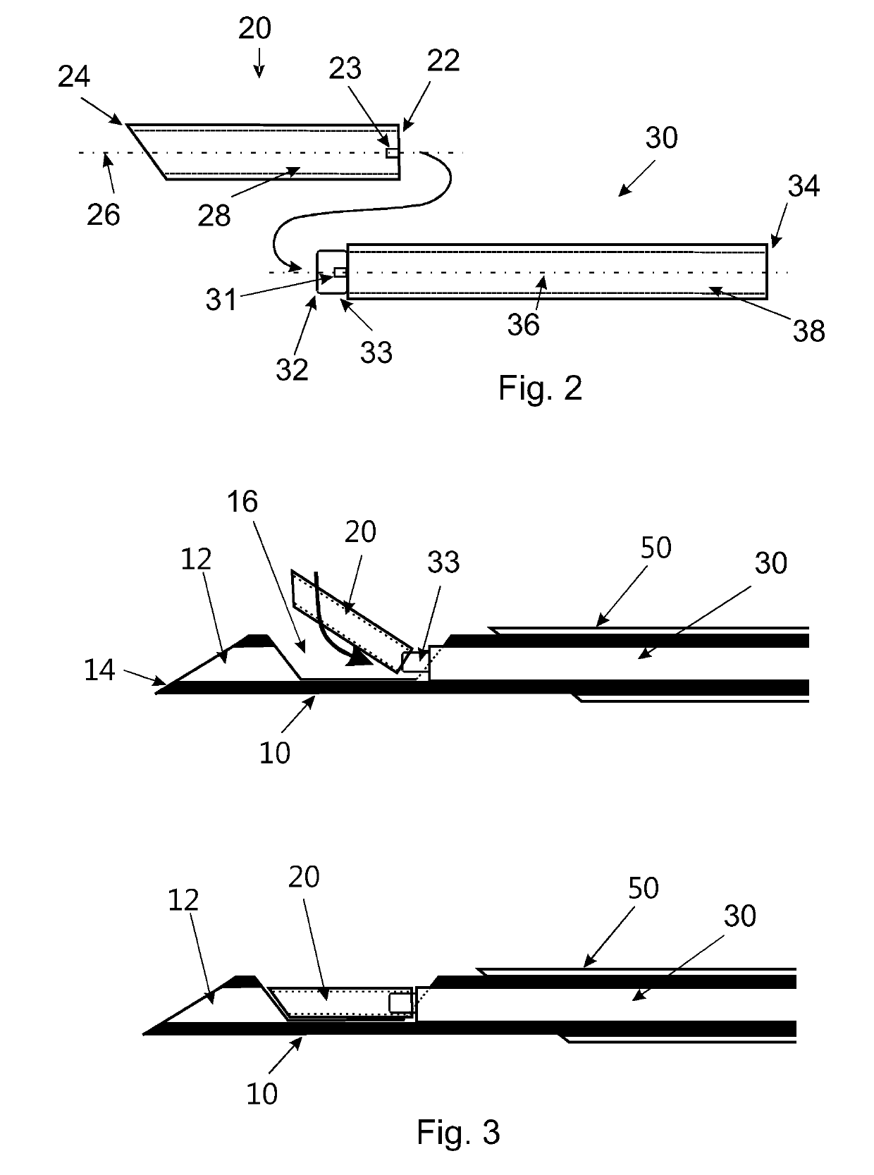
[0046]In FIG. 2, embodiments of a biopsy tube 20 and a tube shaft 30 are shown. The biopsy tube 20 is substantially formed as a hollow cylinder with a substantially circular outer cross section and with first and second ends each having a straight edge. In this embodiment, the first end 22 is formed with an angle of 90° relative to the longitudinal axis 26, i.e. substantially perpendicular to the longitudinal axis. The second end 24 may be formed with an inclined angle relative to the longitudinal axis 26, wherein this angle may be in the range between 45° and 65°, for example 55°. It will be understood that the angles at the ends of the biopsy tube may be adapted to fit to inclined surfaces of a notch formed in a main shaft of a biopsy device, as described in detail below. For example, the length of such a biopsy tube may be between approximately 3 mm and 20 mm, preferably 14 mm + / −5 mm and an outer diameter may be 2 mm, whereas an inner diameter of a channel 28 which extends throu...


PUM


Abstract

A biopsy device for taking a 3D biopsy may comprise an outer sleeve, a hollow main shaft, a biopsy tube and a tube shaft. The hollow main shaft may have a distal end portion with a sideward facing notch, and the main shaft may be adapted to be accommodated within the outer sleeve. The biopsy tube may be provided for receiving cut and thus isolated tissue. A proximal end of the biopsy tube may be releasably attachable to a distal end of the tube shaft so that the biopsy tube is movable together with the tube shaft within the hollow main shaft between a proximal position in which the biopsy tube is not located in the notch, and a distal position in which the biopsy tube is located in the notch.

Description

CROSS-REFERENCE TO PRIOR APPLICATIONS[0001]This application is the U.S. National Phase application under 35 U.S.C. § 371 of International Application No. PCT / EP2015 / 076013, filed on Nov. 9, 2015, which claims the benefit of European Patent Application No. 14192823.4, filed on Nov. 12, 2014. These applications are hereby incorporated by reference herein.FIELD OF THE INVENTION[0002]The invention generally relates to a system for obtaining a 3D biopsy. Particularly, the invention relates to a biopsy device with a biopsy tube maintaining the integrity of an extracted tissue volume.BACKGROUND OF THE INVENTION[0003]For the proper analysis of tumours and defining the appropriate treatment detailed information on a tumour may be needed. First the presence and position of a potential tumour may be identified through medical imaging.[0004]Subsequently a biopsy may be taken to assess whether or not the lesion is benign or malignant through pathology. An exemplary workflow for obtaining a biops...

Claims


Application Information

Patent Timeline
Patent Type & Authority Patents(United States)
IPC IPC(8): A61B10/02A61B1/07A61B5/00A61B10/04
CPCA61B1/07A61B5/0073A61B5/0071A61B10/0275A61B5/0075A61B5/6848A61B5/0084A61B2010/045A61B10/0283
Inventor VAN DER ZAAG, PIETER JANVAN DER VLEUTEN, CORNELIUS ANTONIUS NICOLAAS MARIAHENDRIKS, BERNARDUS HENDRIKUS WILHELMUSLUCASSEN, GERHARDUS WILHELMUSWIJBRANS, KLAAS CORNELIS JAN
Owner KONINKLJIJKE PHILIPS NV
Learn More