Luneburg lens antenna device

a technology of lens antenna and antenna device, which is applied in the direction of individual energised antenna array, resonant antenna, substantially flat resonant elements, etc., can solve the problems of low-frequency mimo antenna and high-frequency mimo antenna not being integrated, and achieve the effect of reducing the size of the entire device and high directivity

Active Publication Date: 2019-11-05
MURATA MFG CO LTD
View PDF16 Cites 9 Cited by
  • Summary
  • Abstract
  • Description
  • Claims
  • Application Information

AI Technical Summary

Benefits of technology

[0010]According to the present disclosure, a patch antenna includes a radiating element disposed on the outer peripheral surface of the Luneburg lens and a ground electrode positioned at a side opposite the Luneburg lens as viewed from the radiating element so as to cover the radiating element. With this configuration, as a result of exciting the radiating element, the patch antenna can radiate radio waves toward the Luneburg lens and radiate beams having high directivity in multiple directions. In this case, plural patch antennas disposed on the outer peripheral surface of the Luneburg lens and at different positions of focal points of the Luneburg lens in the peripheral direction may be formed into an array in the axial direction, for example, and be connected to a corresponding transmit-and-receive circuit. As a result of exciting plural patch antennas disposed at different positions in the peripheral direction, it is possible to form high-gain beams in different directions and also to form multiple beams. As a result of forming plural patch antennas into an array in the axial direction, it is possible to obtain high-frequency MIMO antennas that can radiate beams having directivity which is controlled also in an elevation-angle direction.
[0011]The plural ground electrodes are separately disposed in association with the patch antennas, and form low-frequency antennas which are possible to radiate lower-frequency radio waves than those radiated from the patch antennas. It is thus possible to form low-frequency MIMO antennas by using the plural low-frequency antennas. The high-frequency MIMO antennas and the low-frequency MIMO antennas can be integrated with each other, thereby making it possible to reduce the size of the entire device to be smaller than when the high-frequency MIMO antennas and the low-frequency MIMO antennas are separately formed.
[0014](4) In the present disclosure, a plurality of the patch antennas are formed in a range which is ½ or smaller of an entire range of the Luneburg lens in the peripheral direction. The plural high-frequency patch antennas can thus form low-sidelobe MIMO antennas without necessarily causing blocking in the patch antennas.

Problems solved by technology

In this antenna device, however, a low-frequency MIMO antenna and a high-frequency MIMO antenna are not integrated with each other.

Method used


Image

  • Luneburg lens antenna device
  • Luneburg lens antenna device
  • Luneburg lens antenna device

Examples


Embodiment Construction

[0033]Luneburg lens antenna devices according to embodiments of the present disclosure will be described below in detail with reference to the accompanying drawings.

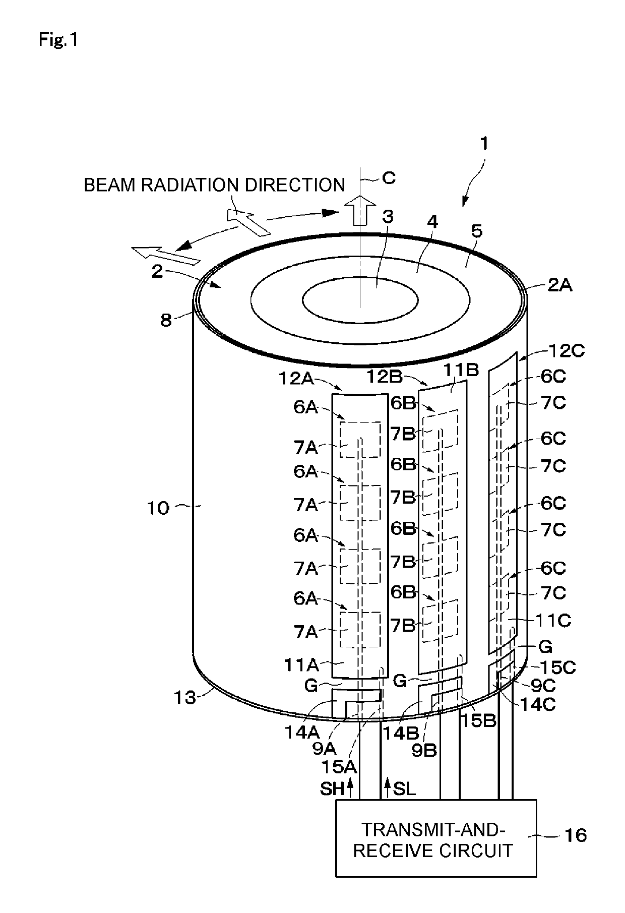
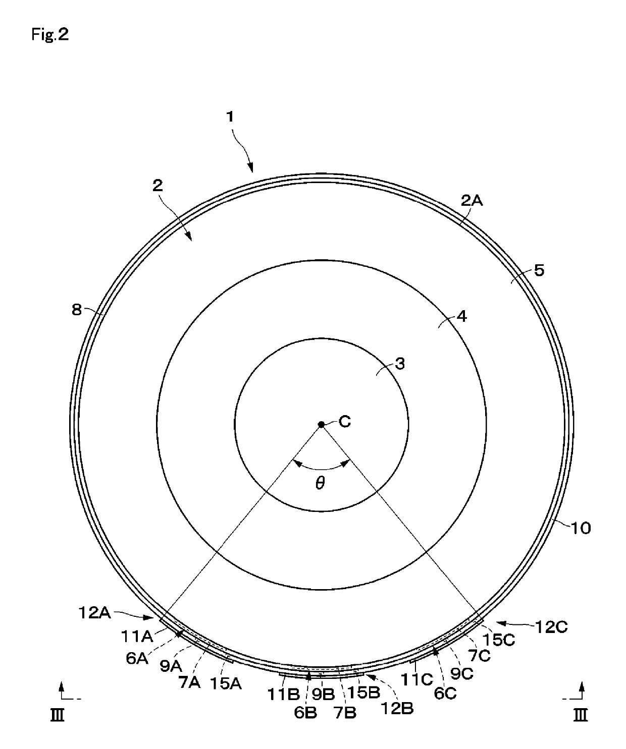
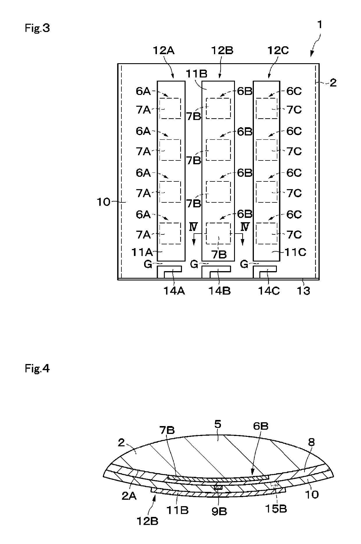
[0034]A Luneburg lens antenna device 1 (hereinafter called the antenna device 1) according to a first embodiment is shown in FIGS. 1 through 12. The antenna device 1 includes a Luneburg lens 2, patch antennas 6A through 6C, and low-frequency antennas 12A through 12C.

[0035]The Luneburg lens 2 and the patch antennas 6A through 6C which form high-frequency MIMO antennas will first be discussed below.

[0036]The Luneburg lens 2 is formed in a cylindrical shape and has a distribution of different dielectric constants in the radial direction. More specifically, the Luneburg lens 2 includes plural (three, for example) dielectric layers 3 through 5 stacked on each other from the center to the outside portion in the radial direction. The dielectric layers 3 through 5 have different dielectric constants ε1 through ε3, respectively, ...


PUM


Abstract

A Luneburg lens antenna device includes a Luneburg lens, a plurality of patch antennas, and a plurality of low-frequency antennas. The Luneburg lens is formed in a cylindrical shape and includes three dielectric layers having different dielectric constants and stacked on each other in the radial direction. The plurality of patch antennas respectively include ground electrodes which cover the outer peripheral surface of radiating elements, and form high-frequency MIMO antennas. The plurality of low-frequency antennas are monopole antennas using the ground electrodes, and form low-frequency MIMO antennas.

Description

[0001]This is a continuation of International Application No. PCT / JP2016 / 085913 filed on Dec. 2, 2016 which claims priority from Japanese Patent Application No. 2016-001691 filed on Jan. 7, 2016. The contents of these applications are incorporated herein by reference in their entireties.BACKGROUNDTechnical Field[0002]The present disclosure relates to a Luneburg lens antenna device including a Luneburg lens.[0003]An antenna device that can receive radio waves from plural satellites by using a Luneburg lens is known (see Patent Document 1, for example). In the antenna device disclosed in Patent Document 1, microwave transmit-and-receive modules (primary radiators) are disposed at positions of focal points of a Luneburg lens. This antenna device receives radio waves from a target satellite as a result of changing the receiving direction of radio waves by shifting the positions of the transmit-and-receive modules.[0004]Patent Document 2 discloses a multiband antenna device which uses gr...

Claims


Application Information

Patent Timeline
Patent Type & Authority Patents(United States)
IPC IPC(8): H01Q3/46H01Q19/06H01Q21/20H01Q15/08
CPCH01Q19/06H01Q15/08H01Q21/20H01Q3/46H01Q1/246H01Q9/0407H01Q9/16H01Q9/40H01Q19/062H01Q21/065H01Q5/35H01Q5/40
Inventor KAWAHATA, KAZUNARI
Owner MURATA MFG CO LTD
Why Eureka
Try Eureka