
Apparatus and method for controlling an internal combustion engine

a control device and internal combustion engine technology, applied in the direction of electric control, combustion engines, machines/engines, etc., can solve the problems of affecting the reduction of nosub>x, and scavenging occurrence, so as to prevent the deterioration of nox purification efficiency and reduce the amount of scavenging during the execution of rich spike control

Active Publication Date: 2019-11-12
TOYOTA JIDOSHA KK
View PDF52 Cites 1 Cited by
  • Summary
  • Abstract
  • Description
  • Claims
  • Application Information

AI Technical Summary

Benefits of technology

[0008]The invention provides a control device for an internal combustion engine that can prevent deterioration of NOx purification efficiency by maintaining the effectiveness of the rich spike control.
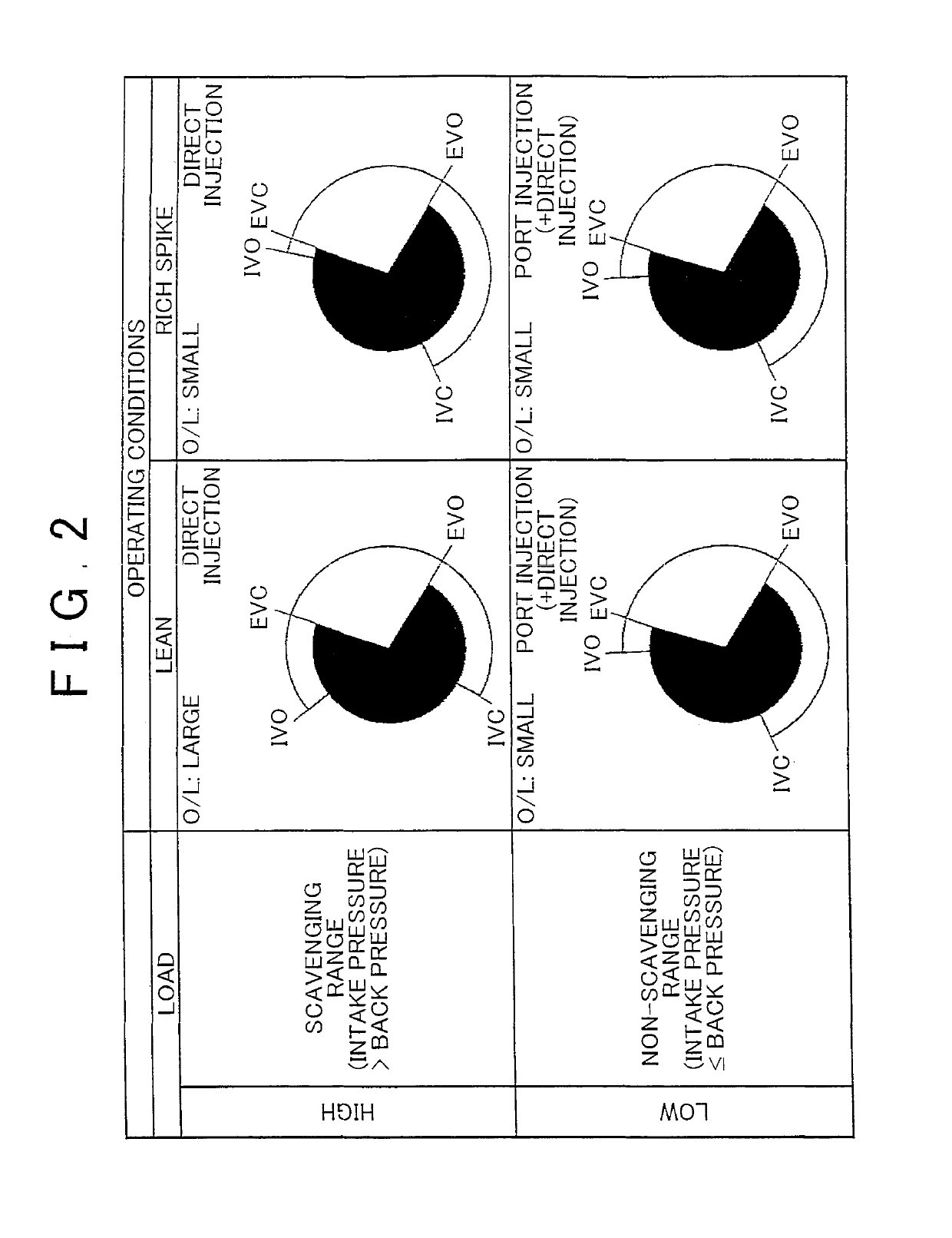
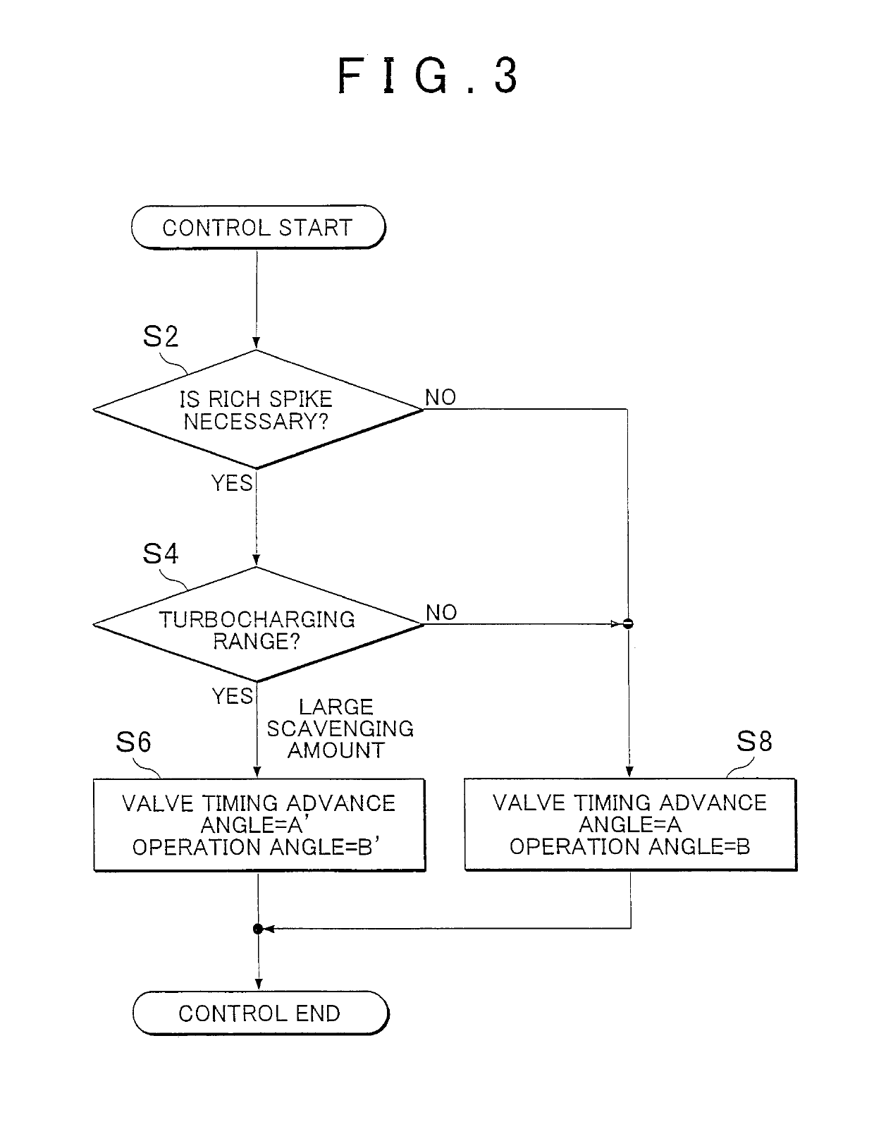
[0011]By decreasing the overlap amount between the intake valve and the exhaust valve, an air amount that flows from the intake port to the exhaust port by scavenging (hereinafter referred to as a scavenging amount) can be reduced. By reducing the scavenging amount during execution, of the rich spike control, a reaction between oxygen and the reduction agents produced by the rich spike control is reduced. At the same time, direct or indirect reaction between the reduction agents and NOx can be promoted.
[0012]In the control device, the electronic control unit may be configured to maintain the overlap amount such that the overlap amount during execution of the rich spike control is the same as the overlap amount during non-execution of the rich spike control, in an operation range where the pressure of the exhaust port becomes higher than the pressure of the intake port. According to this configuration, an operation for varying the overlap amount between the intake valve and the exhaust valve is limited to the operation range where scavenging may occur. Accordingly, deterioration of combustion stability due to the variation in the overlap amount can be prevented.
[0013]In the control device, the electronic control unit may be configured to vary the overlap amount during execution of the rich spike control such that the overlap amount in the operation range where the pressure of the intake port becomes higher than the pressure of the exhaust port is larger than the overlap amount in the operation range where the pressure of the exhaust port becomes higher than the pressure of the intake port. According to this configuration, in the operation range where scavenging may occur, increasing the overlap amount can scavenge residual exhaust gas and improve charging efficiency of fresh air. Further, in the operation range where scavenging does not occur, an internal EGR amount can be reduced by decreasing the overlap amount, and a combustion limit of the lean combustion operation can be pushed up by increasing the rate of fresh-charged air in the cylinder gas.
[0014]In the control device, the electronic control unit may be configured to increase the overlap amount in accordance with advancing of a valve timing of the intake valve, and the electronic control unit may be configured to decrease the overlap amount in accordance with retarding of the valve timing of the intake valve. According to this configuration, when the rich spike control is executed in an operation range where scavenging may occur, the valve timing of the intake valve is retarded in addition to decreasing the overlap amount. Retarding the valve timing of the intake valve can decrease the charging efficiency of fresh air without lowering the pressure of the intake port by throttling the throttle valve. Thus, according to this configuration, when the rich spike control is terminated to return to the lean combustion operation again, the charging efficiency of fresh air can be readily increased.
[0018]According to the above-mentioned control unit, the overlap amount between the intake valve and the exhaust valve is decreased during execution of the rich spike control in the operation range where the pressure of the intake port becomes higher than the pressure of the exhaust port. Accordingly, the scavenging amount during execution of the rich spike control can be reduced. As a result, a reaction between oxygen and the reduction agents produced by the rich spike control is reduced. At the same time, a direct or indirect reaction between the reduction agents and NOx can be promoted to prevent deterioration of the NOx purification efficiency.

Problems solved by technology

However, depending on an operation range of the engine, the rich spike control may not function effectively in some cases.
In particular, in a turbocharged engine, occurrence of scavenging becomes conspicuous when intake pressure is boosted by turbocharging.
As a result, a reaction occurs between oxygen and the reduction agent generated by the rich spike control, and hinders the reduction of NOx by the reduction agent.
As a result, NOx purification efficiency of the exhaust gas control apparatus is deteriorated, which may sometimes lead to discharge of NOx into the atmosphere.

Method used


Image

  • Apparatus and method for controlling an internal combustion engine
  • Apparatus and method for controlling an internal combustion engine
  • Apparatus and method for controlling an internal combustion engine

Examples


first embodiment

[0025]A first embodiment will be described hereinafter with reference to the attached drawings.

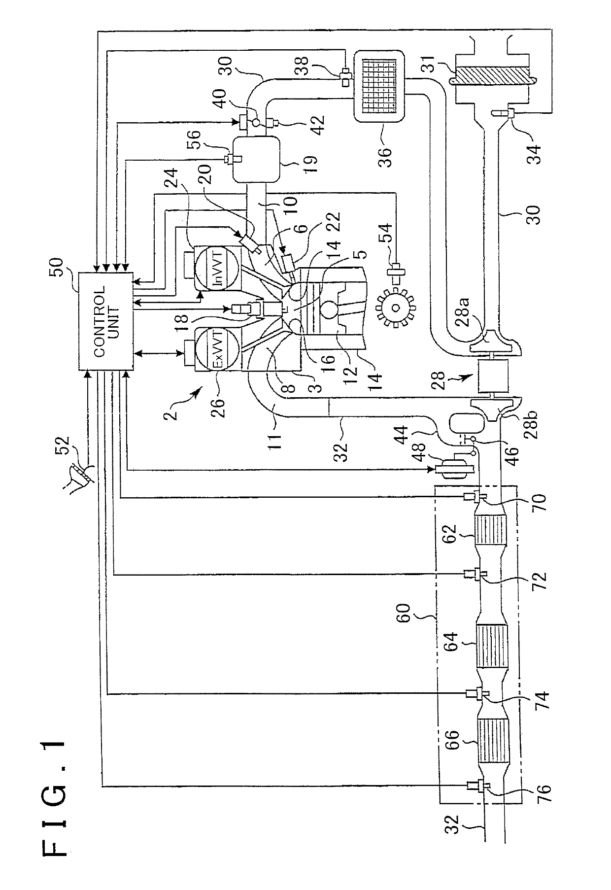
[0026]FIG. 1 is a view that illustrates a system configuration according to the first embodiment of the invention. The system according to this embodiment includes an internal combustion engine (hereinafter simply referred to as the engine) 2 equipped in a vehicle as a power unit. The number of cylinders the engine 2 has and how the cylinders are arranged will not be limited in particular.

[0027]The engine 2 includes a cylinder block 4 having a piston 12 arranged therein and a cylinder head 3. A space defined by the cylinder head 3 and the piston 12 forms a combustion chamber 5. The engine 2 is a spark-ignition type engine, and includes a spark plug 18 of an ignition device, which is attached to the cylinder head 3 such that the spark plug 18 protrudes from a top of the combustion chamber 5. An intake port 6 and an exhaust port 8 formed in the cylinder head 3 are open to the combustion cham...

second embodiment

[0068]Next, the invention will be described with reference to the drawing.

[0069]FIG. 5 is a view that illustrates a system configuration according to the second embodiment of the invention. The system according to this embodiment includes the engine 2 and the control device 50 that controls the engine 2. Since the configuration of the engine 2 and functions of the control device 50 are common to those of the first embodiment, detailed description thereof will be omitted herein. The difference between the system of this embodiment and the system of the first embodiment is the configuration of an exhaust gas control apparatus 80 provided in the exhaust passage 32.

[0070]The exhaust gas control apparatus 80 is constituted by an SC 82 and an NSR 84. The SC 82 is disposed in the exhaust passage on an upstream side thereof, and the NSR 84 is disposed in the exhaust passage on a downstream side thereof. An air-fuel ratio sensor 90 is disposed immediately upstream of the SC 82 in the exhaust...


PUM


Abstract

An engine includes an exhaust gas control apparatus that is configured to store NOx and react NOx with a reduction agent. A control device for the engine includes an electronic control unit. The electronic control unit is configured to: (i) execute a rich spike control, the rich spike control is a control executed to temporarily change an in-cylinder air-fuel ratio from a leaner air-fuel ratio than the stoichiometric air-fuel ratio to the stoichiometric air-fuel ratio or a richer air-fuel ratio than the stoichiometric air-fuel ratio, and (ii) vary an overlap amount of an intake valve and an exhaust valve such that the overlap amount is less during execution of the rich spike control than during non-execution of the rich spike control, in an operation range where a pressure of the intake port becomes higher than a pressure of the exhaust port.

Description

CROSS-REFERENCE TO RELATED APPLICATIONS[0001]This application is a national phase application of International Application No. PCT / 162015 / 002231, filed Nov. 27, 2015, and claims the priority of Japanese Application No. 2014-242035, filed Nov. 28, 2014, the content of both of which is incorporated herein by reference.BACKGROUND OF THE INVENTION1. Field of the Invention[0002]The invention relates to a control device for an internal combustion engine provided with an exhaust gas control apparatus that purifies nitrogen oxides (NOx) in exhaust gas and to a control method thereof.2. Description of Related Art[0003]An exhaust gas control apparatus that purifies NOx is known as an apparatus for controlling NOx emissions in an internal combustion engine operated on a leaner air-fuel ratio than a stoichiometric air-fuel ratio. A NOx storage-reduction catalyst and a selective catalytic reduction catalyst are known as the exhaust gas control apparatus that purifies NOx. The NOx storage-reducti...

Claims


Application Information

Patent Timeline
Patent Type & Authority Patents(United States)
IPC IPC(8): F02D41/02F02B37/013F02B37/00F02B37/16F02B29/04F02D41/22F02D41/40F02D13/02F02D41/00F02B27/02F02B27/00
CPCF02B29/04F02D41/40F02D41/0275F02D41/221F02B37/004F02B37/013F02D13/0203F02D13/0261F02B37/162F02B27/0294F02D41/0007Y02T10/146F02D2200/0614Y02T10/144F02D41/00F02D2041/001F02D2200/0406Y02T10/18F02B27/00F02D2200/101Y02T10/44Y02T10/12Y02T10/40
Inventor HOTTA, SHINTARO
Owner TOYOTA JIDOSHA KK
Learn More