Variable flow-through cavitation device

a cavitation device and variable technology, applied in the field of flow-through, high-shear mixers and cavitation apparati, can solve the problems of insufficient efficiency of sonic or ultrasonic processing performed in a static vessel, localized increase in pressure and temperature, formation of cavitation bubbles, etc., to achieve high treatment efficiency, rapid mass transfer, and superior capacity

Active Publication Date: 2019-12-17
CAVITATION TECH
View PDF7 Cites 1 Cited by
  • Summary
  • Abstract
  • Description
  • Claims
  • Application Information

AI Technical Summary

Benefits of technology

[0010]The present invention provides a unique method for manipulating fluids. This goal is achieved via the adjustment of the flow section of nozzles design of a multi-stage flow-through cavitation mixing device aimed at the expeditious control of hydrodynamic cavitation. In accordance with the present invention, the method comprises feeding fluidic flow with a discharge pump and / or a downstream suction pump set at proper pressure in an array of low-pressure and high-pressure chambers separated with vortex turbulizers to afford the compact adjustment of the flow section of multi-jet nozzles design, advanced turbulithation, rapid mass transfer, high treatment efficiency and superior capacity, and supplying other conditions of choice.
[0012](1) to provide a compact flow-through cavitation device for processing fluids in an expedited manner with control of hydrodynamic cavitation, optimized energy and maintenance costs;
[0013](2) to reduce space taken up by the processing equipment;
[0016](5) to provide a compact, adjustable flow section of multi-jet nozzles, flow-through device for manipulating fluids at the site of production;
[0023]The present invention is also directed to a process for controlling hydrodynamic cavitation in a fluid using the variable flow-through cavitation device described above. The process begins with fully aligning the plurality of first channels with the plurality of second channels, wherein a flow cross-section of the through channels in the variable multi-jet nozzle is maximized. A fluid is then pumped through the flowpath at a pre-determined pump pressure of between 25 and 5,000 psi. Pumping the fluid through the variable multi-jet nozzles results in the generation of hydrodynamic cavitation. The intensity of the hydrodynamic cavitation generated in the fluid is then measured. Finally, the rotatable shaft is adjusted such that the plurality of first channels are no longer fully aligned with the plurality of second channels and the flow cross-section of the through channels in the variable multi-jet nozzle is reduced. This adjustment of the rotatable shaft changes the intensity of the hydrodynamic cavitation generated in the fluid, which is controlled through the reduction of the flow-cross-section.

Problems solved by technology

The eventual collapse of the bubbles results in an localized increase in pressure and temperature.
When fluid is processed in a flow-through cavitation mixing device at a suitable velocity, the decrease in hydrostatic pressure results in the formation of cavitation bubbles.
The efficiency of sonic or ultrasonic processing performed in a static vessel is insufficient because the effect diminishes with an increase in distance from the radiation source.
The achieved fluid alterations are not uniform and occur at specific locations in the vessel, depending on the frequency and interference patterns.
Thus, processing fluids via sonic or ultrasonic cavitation does not offer an optimized method.
However, the prior art techniques do not offer the most efficient and safest methods of blending, emulsifying, altering or upgrading fluids in the shortest time possible.

Method used


Image

  • Variable flow-through cavitation device
  • Variable flow-through cavitation device
  • Variable flow-through cavitation device

Examples


example 1a

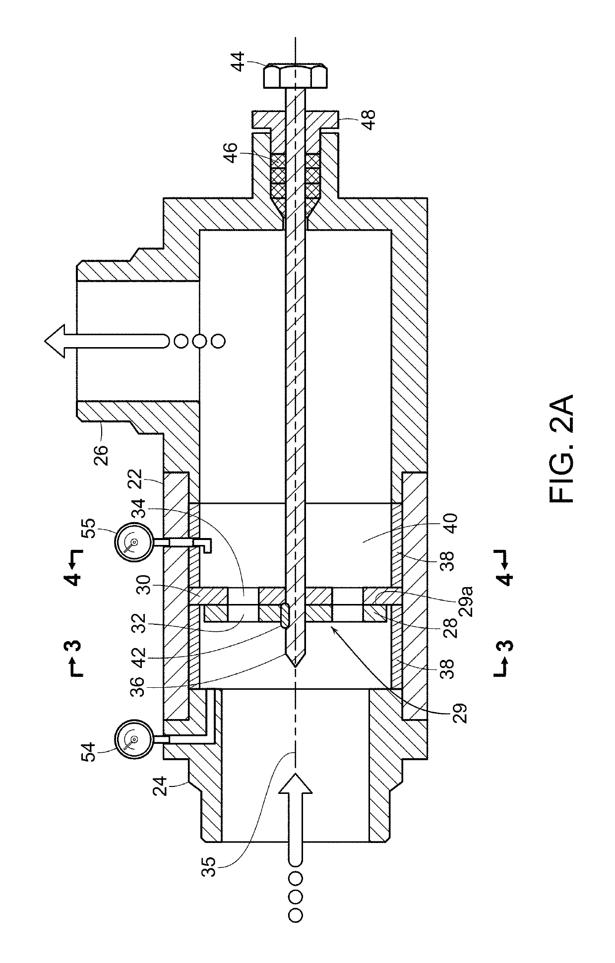
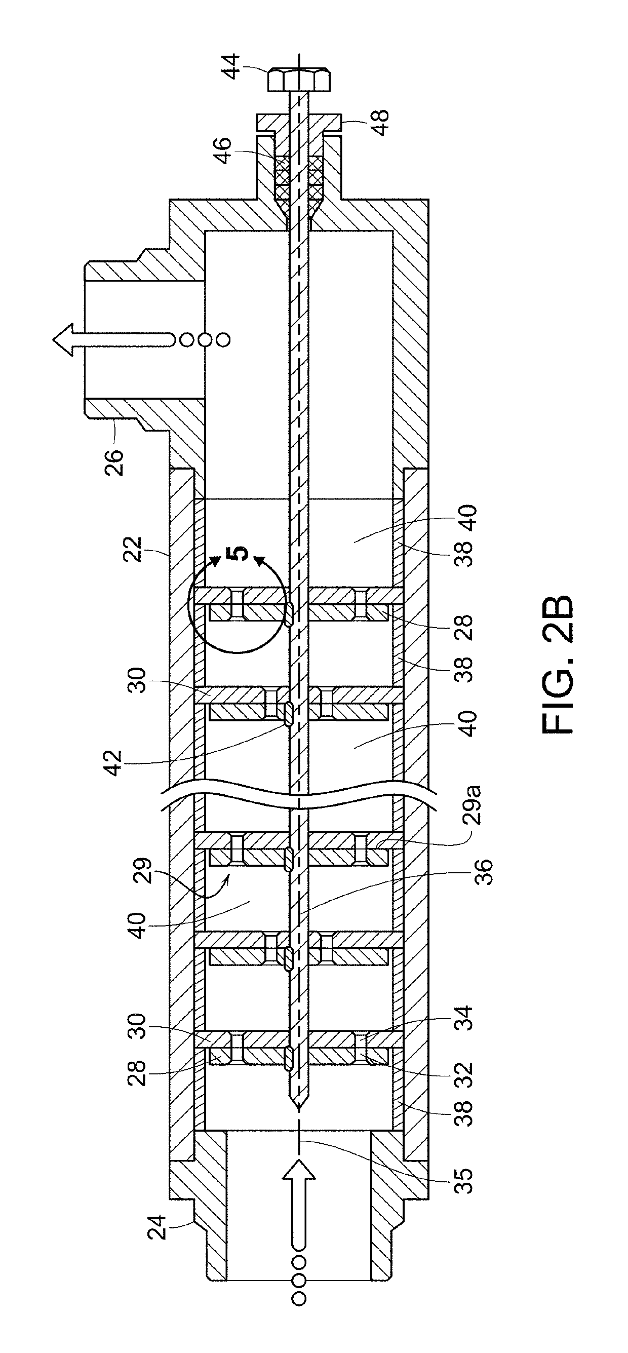
[0080]Values for cavitation number, calculated with the specialized software ANSYS for the cavitation device 20 (length 70 cm, diameter 6 cm, 10 multi-jet nozzles) which is similar to the apparatus shown in FIG. 2B. The calculation was performed for the initial position of disks 28 and 30 at fully aligned channels 32 and 34 (FIG. 6A). The channels have the Venturi tube profile in a longitudinal section (FIG. 5D). The device 20 was operated at a flow rate of 50 gpm and an inlet pressure of 272 psi. The calculation results at 25 C are shown in FIG. 9A in the form of water flow lines. Cavitation numbers were calculated for each working chamber 40 following a variable multi-jet nozzle 29, and had values of 0.752, 0.645, 0.818, 0.611, 0.583, 0.442, 0.353, 0.254, 0.154, and 0.127, respectively, assuming flow moves from left to right.

example 1b

[0081]Values for cavitation number, calculated with the specialized software ANSYS for the cavitation device 20 (length 70 cm, diameter 6 cm, 10 multi-jet nozzles) which is similar to the apparatus shown in FIG. 2B. The calculation was performed for the position of disks 28 rotated by 5 degrees relative to disk 30 from the fully aligned position. Channels 32 and 34 are partially offset from each other, as in the example shown in FIG. 6B. The channels have the Venturi tube profile in the longitudinal section (FIG. 5D). The device 20 was operated at a flow rate of 40 gpm and an inlet pressure of 279 psi. The calculation results are shown in FIG. 9B in the form of water flow lines at 25 C. Cavitation numbers were calculated for each working chamber 40 following a variable multi-jet nozzle 29, and had values of 0.798, 0.700, 0.872, 0.656, 0.612, 0.578, 0.406, 0.312, 0.168, and 0.117, respectively, assuming flow moves from left to right.

example 1c

[0082]Values for cavitation number, calculated with the specialized software ANSYS for the cavitation device 20 (length 70 cm, diameter 6 cm, 10 multi-jet nozzles) which is similar to the apparatus shown in FIG. 2B. The calculation was performed for the position of disks 28 rotated by 18 degrees relative to disk 30 from the fully aligned position. Channels 32 and 34 are partially offset from each other, as similar to the example shown in FIG. 6B. The channels have the Venturi tube profile in longitudinal section (FIG. 5D). The device 20 was operated at a flow rate of 20 gpm and an inlet pressure of 275 psi. The calculation results are shown in FIG. 9C in the form of water flow lines at 25 C. Cavitation numbers were calculated for each working chamber 40 following a variable multi-jet nozzle 29, and had values of 0.801, 0.715, 0.813, 0.701, 0.577, 0.431, 0.328, 0.205, 0.125, and 0.010, respectively, assuming flow moves from left to right.

[0083]As seen from the calculation results sho...


PUM

PropertyMeasurementUnit
particle sizesaaaaaaaaaa
temperatureaaaaaaaaaa
pressureaaaaaaaaaa

Abstract

A flow-through cavitation device having an elongated housing with an inlet and an outlet. One or more variable multi-jet nozzles are disposed throughout the elongated housing with a working chamber following each variable multi-jet nozzle. Each variable multi-jet nozzle consists of a movable disk fixedly mounted on a central shaft and a stationary disk fixedly mounted on the housing and in contact with the rotating disk. The movable and stationary disks of each variable multi-jet nozzle have through channels. The flow cross-sectional area of the through channels is variable by rotating the movable disk relative to the stationary disk.

Description

BACKGROUND OF THE INVENTION[0001]The invention generally relates to the flow-through, high-shear mixers and cavitation apparati that are utilized for processing heterogeneous and homogeneous fluidic mixtures through the controlled formation of cavitation bubbles and uses the energy released upon the implosion of these bubbles to alter said fluids. The device is meant for preparing mixtures, solutions, emulsions and dispersions with the particle sizes that can be smaller than one micron, particle and nanoparticle synthesis and improving composition, mass and heat transfer and is expected to find applications in pharmaceutical, food, oil, chemical, fuel and other industries.[0002]More particularly, the device relates to the modification of fluids composed of different compounds by using the implosion energy of cavitation bubbles to improve the homogeny, viscosity, and / or other physical characteristics of the fluids, as well as, alter their chemical composition, and obtain upgraded or ...

Claims


Application Information

Patent Timeline
Patent Type & Authority Patents(United States)
IPC IPC(8): B01F5/00B01F5/06B01F3/08
CPCB01F5/0688B01F2215/0036B01F2003/0842B01F23/41B01F25/45212B01F25/4521B01F33/811B01F23/4145B01F2101/2204
Inventor GORDON, ROMANGORODNITSKY, IGORPROMTOV, MAXIM A.VOLOSHIN, NAUM
Owner CAVITATION TECH
Why Eureka
Try Eureka