
Robust magnet field homogeneity and detected signal-to-noise for transmission park position sensor applications

Active Publication Date: 2020-01-07
GM GLOBAL TECH OPERATIONS LLC
View PDF6 Cites 2 Cited by
  • Summary
  • Abstract
  • Description
  • Claims
  • Application Information

AI Technical Summary

Benefits of technology

The patent text describes a need for magnetic materials that can be used in transmissions and position sensors, and which have precise control over their magnetic field directionality. Current magnetic materials tend to rotate and become misaligned, which can cause inaccurate position detection. The technical effect of the patent is to provide magnetic materials that can be retrofitted into existing transmissions and position sensors, and which have high magnetic field strength and precise control over their magnetic field directionality, to increase the accuracy and precision of measurements taken by the position sensors.

Problems solved by technology

For example, an engine ignition system may be disabled in an out-of-park position.
Accordingly, if the direction of magnetic polarization of the magnetic materials is offset from the axis of the cylindrical orifice, the direction of the magnetic field sensed by the transmission position sensors may detect an inaccurate or erroneous position.
Thus, it can be difficult to limit the rotation of the magnetic materials and the axial tilt of the magnetic field polarization of those magnetic materials to such an extent that the potential for transmission position sensors to accurately detect the position of the magnetic materials is adequately low.

Method used


Image

  • Robust magnet field homogeneity and detected signal-to-noise for transmission park position sensor applications
  • Robust magnet field homogeneity and detected signal-to-noise for transmission park position sensor applications
  • Robust magnet field homogeneity and detected signal-to-noise for transmission park position sensor applications

Examples


Embodiment Construction

[0034]Reference will now be made in detail to several embodiments of the disclosure that are illustrated in accompanying drawings. Whenever possible, the same or similar reference numerals are used in the drawings and the description to refer to the same or like parts or steps. The drawings are in simplified form and are not to precise scale. For purposes of convenience and clarity, directional terms such as top, bottom, left, right, up, over, above, below, beneath, rear, and front, may be used with respect to the drawings. These and similar directional terms are not to be construed to limit the scope of the disclosure.

[0035]Example embodiments are provided so that this disclosure will be thorough, and will fully convey the scope to those who are skilled in the art. Numerous specific details are set forth such as examples of specific components, devices, and methods, to provide a thorough understanding of embodiments of the present disclosure. It will be apparent to those skilled in...


PUM


Abstract

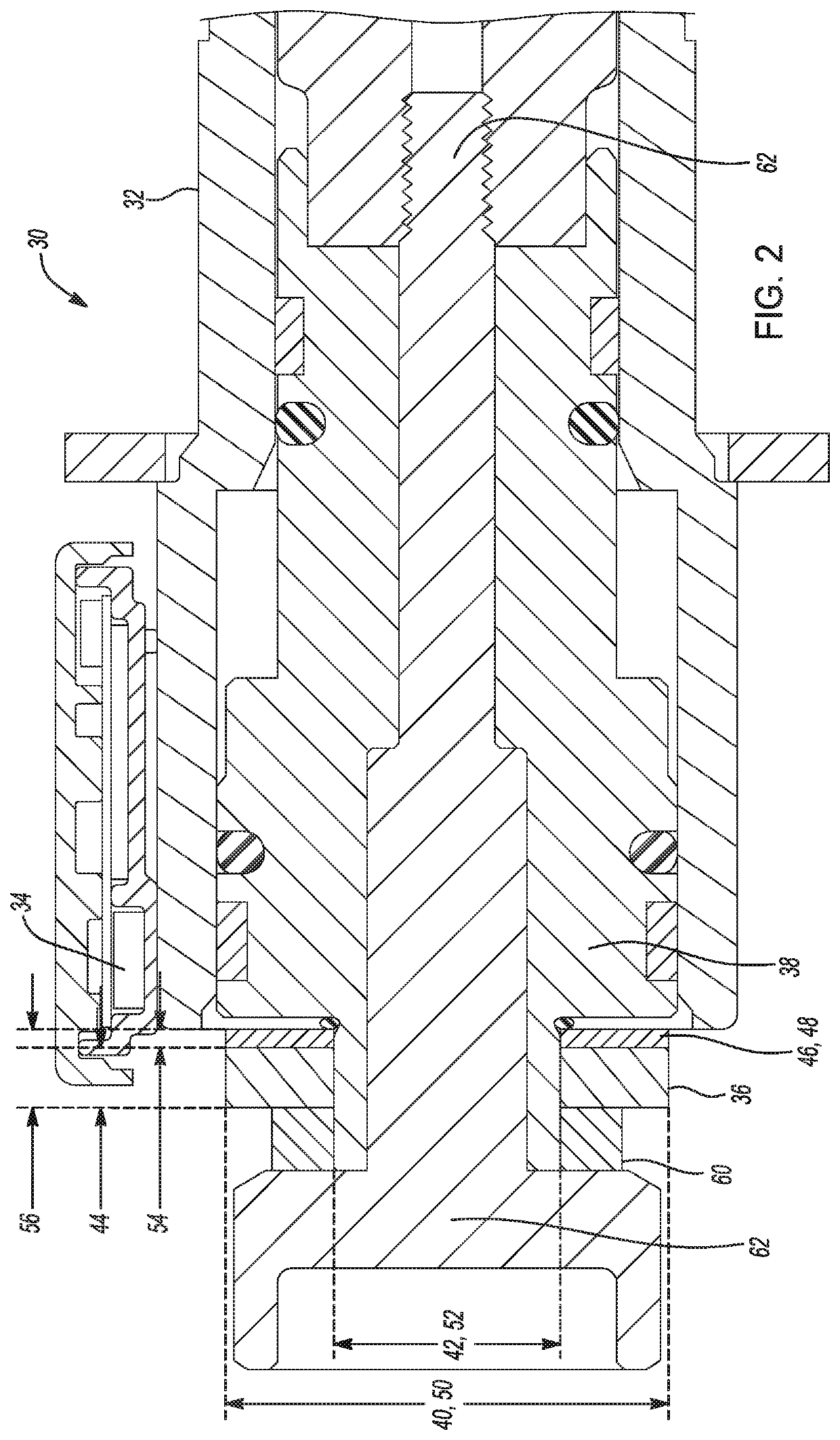
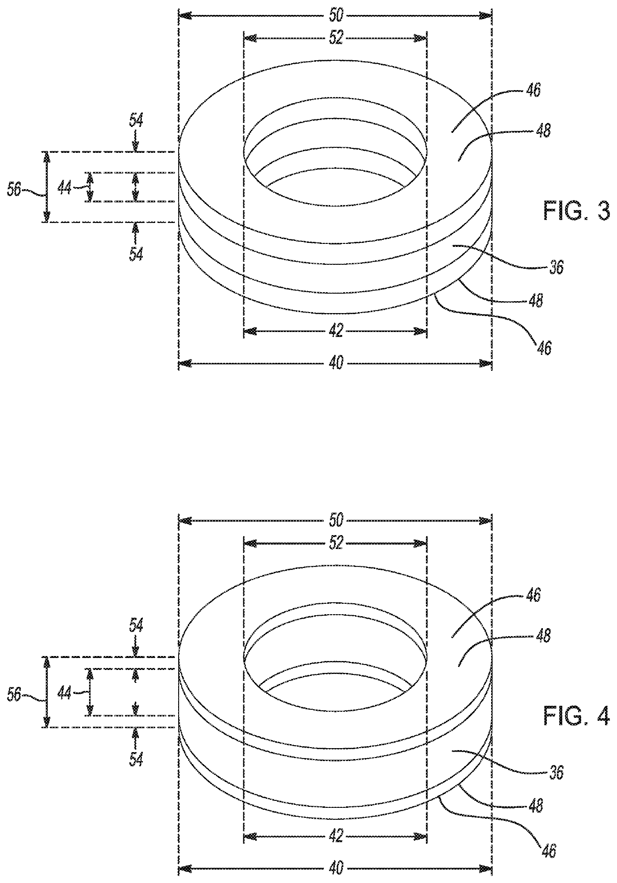
An electronic transmission range selection (ETRS) system for a motor vehicle transmission includes an ETRS housing disposed on the transmission, the ETRS housing having a magnetic field sensor in communication with a transmission controller; and a magnetic field source including a magnet component and a high magnetic permeability component. The magnetic field source disposed on a transmission selector shaft, the magnetic field source detectable by the magnetic field sensor at a plurality of predetermined positions along a movement path of the transmission selector shaft; and the magnetic field sensor detecting magnetic flux generated by the magnetic field source, and communicating magnetic field source position information to the controller. The high magnetic permeability component homogenizes the magnetic flux generated by the magnet component and the controller generates an electronic transmission mode signal based on the magnetic field source position information.

Description

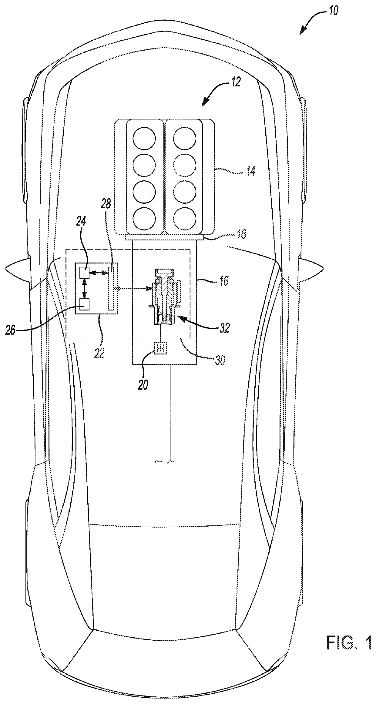
INTRODUCTION[0001]The statements in this section merely provide background information relating to the present disclosure, and may not constitute prior art.[0002]The present disclosure generally relates to motor vehicles, and more specifically to range selection sensors of motor vehicle transmissions. Many vehicles prevent or allow operations of certain functions when a transmission of the vehicle is positioned in an out-of-park position. For example, an engine ignition system may be disabled in an out-of-park position. In order to determine if the transmission is positioned in the out-of-park position, the vehicle may be equipped with a transmission position sensor, which senses the position of one or more components of a transmission control system. The position of the transmission may be communicated to one or more vehicle controllers to either enable or disable various vehicle functions as appropriate. The range selection sensors of the motor vehicle transmission often determine...

Claims


Application Information

Patent Timeline
IPC IPC(8): F16H59/10G01D5/20
CPCF16H59/105G01D5/20F16H59/02F16H59/08F16H61/0204F16H61/0213F16H61/28F16H2059/0221G01D5/145
Inventor WAGNER, SEAN R.PERRY, THOMAS A.STARK, DAVID T.
Owner GM GLOBAL TECH OPERATIONS LLC
Learn More