
Heat exchanger element, manufacturing method therefor, and heat exchanger

a heat exchanger and manufacturing method technology, applied in the direction of heat exchanger fastening, heat exchange apparatus, light and heating apparatus, etc., can solve the problems of difficulty in machining of heat resistant metal, high cost, high density and high weight, etc., to facilitate heat transfer and improve temperature efficiency

Active Publication Date: 2020-01-07
NGK INSULATORS LTD
View PDF45 Cites 0 Cited by
  • Summary
  • Abstract
  • Description
  • Claims
  • Application Information

AI Technical Summary

Benefits of technology

The arrangement of honeycomb structures with gaps enhances heat transfer efficiency and reduces production costs by simplifying the manufacturing process while maintaining high temperature efficiency and heat resistance.

Problems solved by technology

However, for exchanging heat with gas such as automobile exhaust gas, it is difficult to use a general metal heat exchanger at high temperature because of poor heat resistance.
Though a heat exchanger made of heat resistant metal is known, heat resistant metal has problems of difficulty in machining, high density and high weight, and low heat conduction in addition to high price.
However, since the Patent Documents 1 and 2 have poor productivity because of a large number of steps such as plugging and slit-forming, the costs are high.
In addition, since the passages of gas / liquid are disposed in every other row, the piping structure and seal structure of the fluid become complex.
Further, since a coefficient of heat conductivity of liquid is generally 10 to 100 times larger than gas, the heat transfer area on the gas side is insufficient in these techniques, and the heat exchanger becomes large in proportion to the heat transfer area of the gas which limits the heat exchanger performance.
However, since these have poor productivity, the costs tend to be high.

Method used


Image

  • Heat exchanger element, manufacturing method therefor, and heat exchanger
  • Heat exchanger element, manufacturing method therefor, and heat exchanger
  • Heat exchanger element, manufacturing method therefor, and heat exchanger

Examples


example

[0125]Hereinbelow, the present invention will be described in more detail on the basis of Examples. However, the present invention is by no means limited to these Examples.

[0126]1. Manufacturing of Heat Exchanger

(Preparation of Kneaded Material)

[0127]With 100 parts by mass of a SiC powder having an average particle diameter of 35 μm, 4 parts by mass of a binder and water were mixed, and they were kneaded with a kneader to obtain a kneaded material. The kneaded material was put in a vacuum kneader to obtain a circular cylindrical kneaded material.

[0128](Extrusion Forming)

[0129]Next, the kneaded material was extruded to form a honeycomb formed body. In the extrusion, by selecting a die and a jig having appropriate forms, the shape and thickness of the outer peripheral wall 7 and the thickness of partition walls 4, the shape of the cells 3, the cell density, etc., were made desirable. The die made of superhard alloy which hardly abrades away was employed. Regarding the honeycomb formed...


PUM

PropertyMeasurementUnit
porosityaaaaaaaaaa
degree of freedomaaaaaaaaaa
thicknessaaaaaaaaaa

Abstract

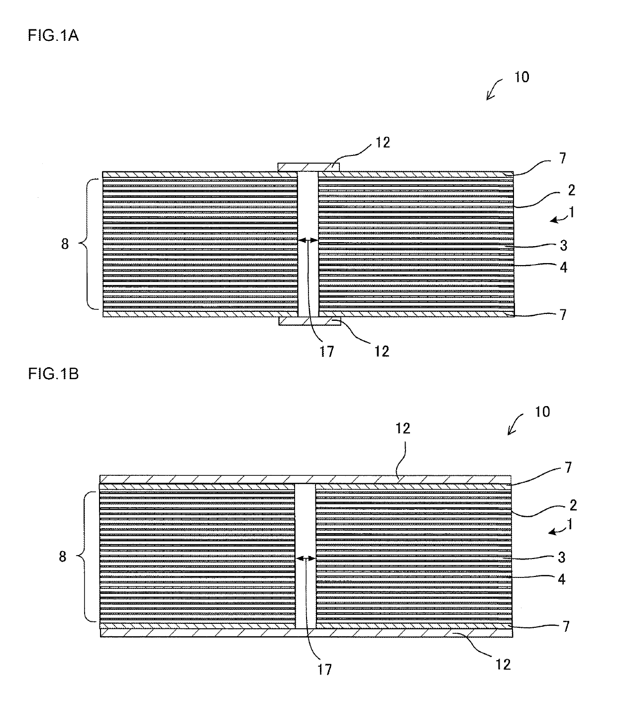
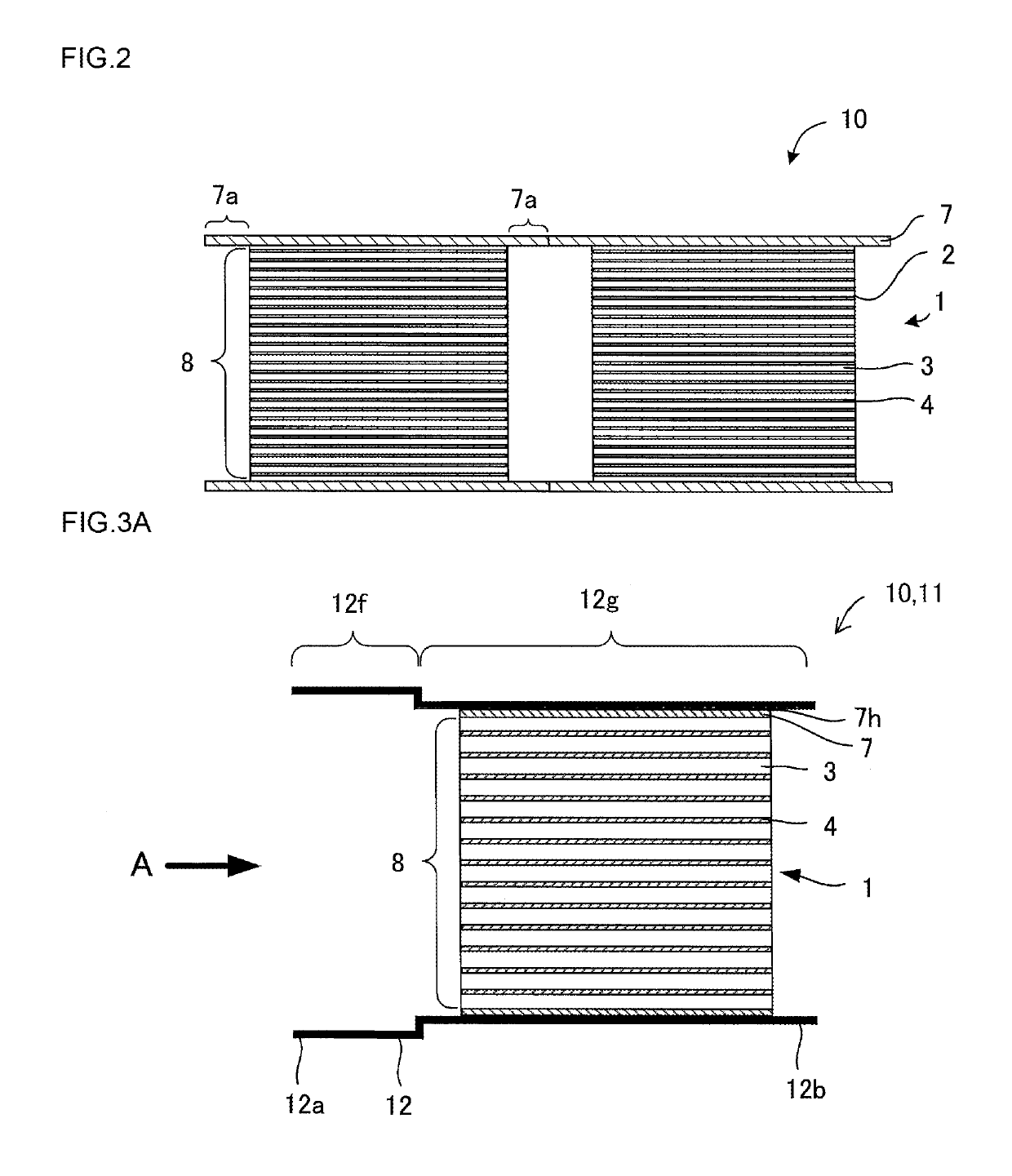
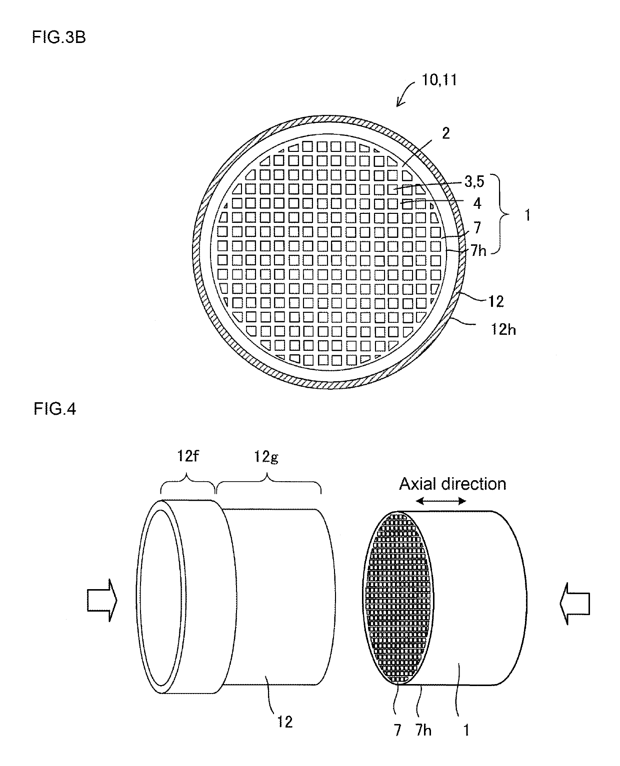
A heat exchanger element includes at least two honeycomb structures arranged serially and each including a cell structural portion having cells separated and formed by partition walls containing SiC and functioning as passages which extend from one end face to the other end face and which a first fluid passes through, and an outer peripheral wall disposed on the outer periphery of the cell structural portion. The first fluid passes through the cells of the honeycomb structures without leaking out of the cells or mixing. The cell structural portions of at least a pair of the honeycomb structures adjacent to each other among the honeycomb structures arranged serially are disposed with a gap, and the first fluid passing through the cells mixes together between end faces forming the gap.

Description

BACKGROUND OF THE INVENTION1. Field of the Invention[0001]The present invention relates to a heat exchanger element for transferring the heat of the first fluid (high temperature side) to the second fluid (low temperature side), a manufacturing method therefor, and a heat exchanger including the heat exchanger element.2. Description of Related Art[0002]For improving fuel consumption of an automobile, there have been demanded techniques of recovering heat from high temperature gas such as combustion exhaust gas of an engine or the like and effectively using it or cooling exhaust gas upon recirculating exhaust gas to the engine admission side. In addition, there has been demanded a gas / liquid heat exchanger for exchanging heat between high temperature gas such as exhaust gas and liquid such as cooling water. As a gas / liquid heat exchanger, fin-provided tube type heat exchangers of an automobile radiator and an air-conditioning outdoor unit are general. However, for exchanging heat wit...

Claims


Application Information

Patent Timeline
Patent Type & Authority Patents(United States)
IPC IPC(8): F28F21/08F28F21/04F28F7/02B23P15/26
CPCF28F7/02B23P15/26F28F21/04F28F21/081F28F2275/14Y10T29/4935
Inventor SUZUKI, YOSHIOTAKAHASHI, HIRONORIKAWAGUCHI, TATSUOKONDO, YOSHIMASA
Owner NGK INSULATORS LTD
Learn More