Acoustic transducers in haptic systems

a technology of haptic systems and acoustic transducers, which is applied in the field of improved calibration techniques of haptic acoustic transducers, can solve the problems of limiting the level of acoustic control that can be obtained in the center of the surface, increasing the cost of the array, and increasing the complexity of the array

Active Publication Date: 2020-01-07
ULTRAHAPTICS IP LTD
View PDF110 Cites 21 Cited by
  • Summary
  • Abstract
  • Description
  • Claims
  • Application Information

AI Technical Summary

Problems solved by technology

This is problematic as existing screen and interactive surface technologies are not acoustically permeable.
But this “active bezel” approach limits the level of acoustic control that can be obtained in the center of the surface.
This problem becomes exaggerated as screen size increases.
Further, the cost, bulk and added complexity of creating an array around the edge of a surface are all problems that limit the uptake and scope of mid-air haptic technology.
Further, in all transducers, even those produced specifically for this use case, small deviations in the offset of the complex phasor from the input signal is not addressed.
Individual manufacturing variation, however, may cause deviations from this idealized model.
Further, all components have limited lifespans.
Phased array systems may have potentially hundreds or even thousands of individual transducer elements, many of which will likely fail before the product incorporating the transducers reaches end-of-life.
True phase delays also exist, wherein manufacturing variability generates offsets in input to output timings.
In addition, the algorithms are able to take unresponsive transducers into account in their computation.
While this may only be hypothetically zero, it may still result in reduced signal-to-noise ratio in calibration measurements.

Method used


Image

  • Acoustic transducers in haptic systems
  • Acoustic transducers in haptic systems
  • Acoustic transducers in haptic systems

Examples


Embodiment Construction

[0020]Described herein are certain techniques for improved acoustic transducers in haptic systems. Some or all of these techniques may be used at the same time or one after the other in order to improve such operation.

I. Integrating Acoustic Transducers into Interactive Surfaces

[0021]1. Transparent or Invisible Acoustic Transducers

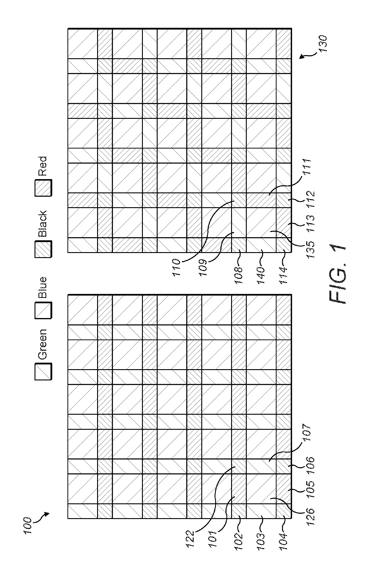
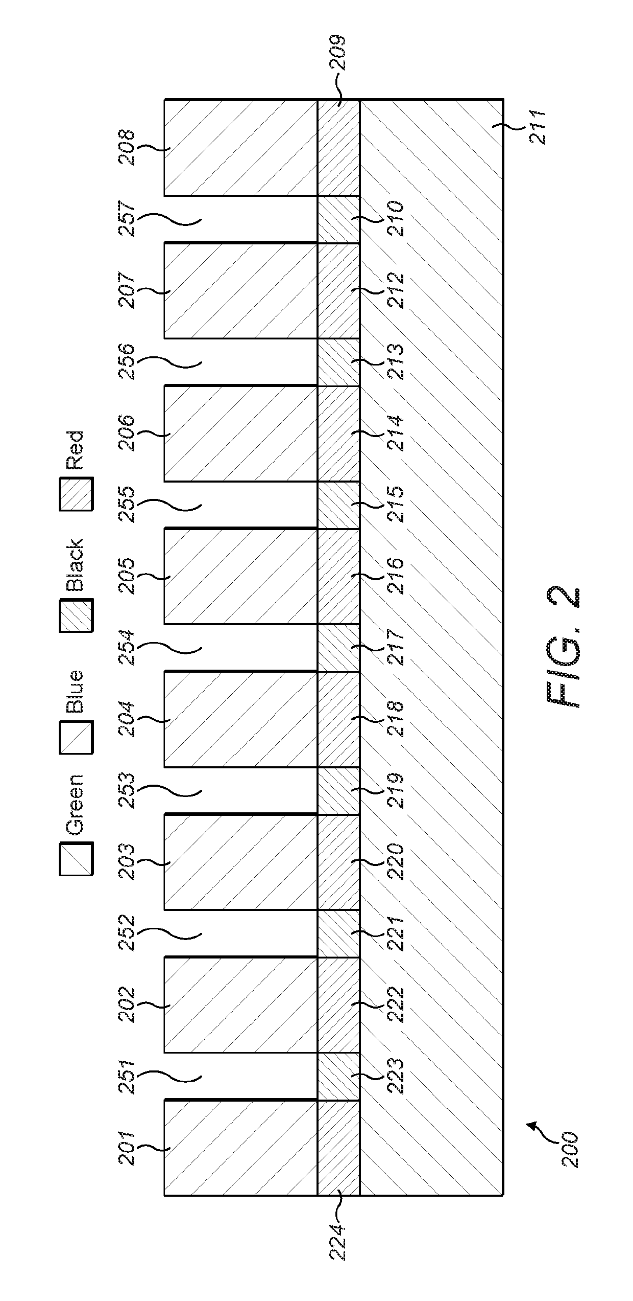
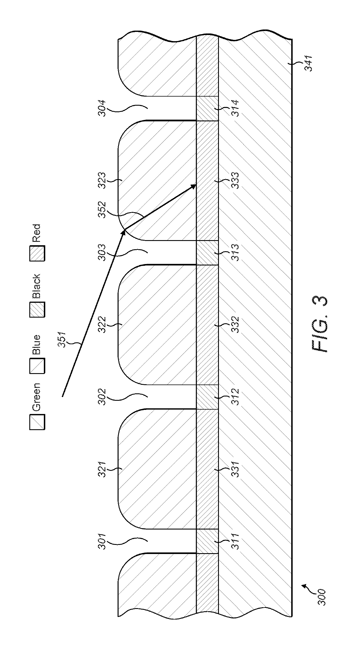
[0022]The acoustic elements may be made to be transparent and added on top of the screen surface as an extra layer. This may be achieved by sandwiching multiple thin layers of a transparent conductor, such as indium tin oxide (ITO), with another transparent piezoelectric material such as those based on bismuth titanate. Driving circuitry may also be integrated transparently, by using existing thin film transistor (TFT) technology. Alternatively, the piezoelectric material may be opaque and deposited around the edge of another transparent, light emitting or optically active element or group of elements. By doing this, it is possible to allow this area to vi...


PUM


Abstract

Described is a screen surface layer comprising a plurality of light-emitting pixels including a plurality of red pixels, a plurality of green pixels and a plurality of blue pixels; a transducer layer comprising a plurality of acoustic transducers, wherein the transducer layer is affixed below the screen surface layer; and a cover layer having a plurality of cylinder-shaped perforations, wherein the cover layer is affixed above the screen surface layer. In addition, an average “transducer model” describing a phasor distribution in space may be produced describing the output signal at the carrier frequency in the air at a known spatial offset from an averaged transducer. Further, phased array systems may have numerous individual transducer elements that will likely fail before the product incorporating the transducers reaches end-of-life. By detecting such failed transducers, the transducer array may function at peak performance by working around the missing transducer output.

Description

RELATED APPLICATION[0001]This application claims the benefit of the following two U.S. Provisional Patent Applications, all of which are incorporated by reference in their entirety:[0002]1) Ser. No. 62 / 351,621, filed on Jun. 17, 2016; and[0003]2) Ser. No. 62 / 370,955, filed on Aug. 4, 2016.FIELD OF THE DISCLOSURE[0004]The present disclosure relates generally to improved calibration techniques for acoustic transducers in haptic-based systems.BACKGROUND[0005]A continuous distribution of sound energy, referred to as an “acoustic field”, may be used for a range of applications including parametric audio and the levitation of objects.[0006]By defining one or more control points in space, the acoustic field can be controlled. Each point may be assigned a value equating to a desired amplitude at the control point. A physical two-dimensional array of transducers may then be controlled to create an acoustic field exhibiting the desired amplitude at the control points. This may be achieved by ...

Claims


Application Information

Patent Timeline
Patent Type & Authority Patents(United States)
IPC IPC(8): H04R29/00G06F3/01H04R17/00H04R1/40H04R3/12G08B6/00
CPCH04R29/002H04R17/00H04R1/403G06F3/016H04R1/406H04R3/12G08B6/00H04R17/005H04R2201/401
Inventor LONG, BENJAMIN JOHN OLIVERCARTER, THOMAS ANDREWKAPPUS, BRIAN
Owner ULTRAHAPTICS IP LTD
Why Eureka
Try Eureka