Power supply apparatus and image forming apparatus

a technology of power supply apparatus and image forming apparatus, which is applied in the direction of electric variable regulation, process and machine control, instruments, etc., can solve the problems of insufficient withstanding voltage of peripheral components and the increase of voltage at the vcc terminal, and achieve the effect of reducing the degree of output voltage chang

Active Publication Date: 2020-01-28
CANON KK
View PDF11 Cites 3 Cited by
  • Summary
  • Abstract
  • Description
  • Claims
  • Application Information

AI Technical Summary

Benefits of technology

[0008]An aspect of the present invention is a power supply apparatus that can reduce the degree of change of output voltage from an auxiliary winding due to a load.

Problems solved by technology

In this case, the increase rate of the voltage at the Vcc terminal under heavy load also increases, leading to insufficient withstanding voltages of peripheral components.

Method used


Image

  • Power supply apparatus and image forming apparatus
  • Power supply apparatus and image forming apparatus
  • Power supply apparatus and image forming apparatus

Examples


first embodiment

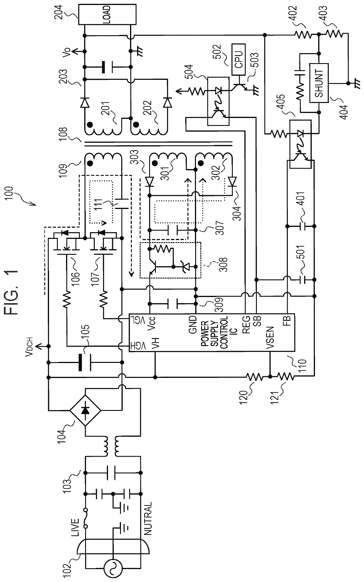
[0025]FIG. 1 illustrates a main circuit diagram of a current-resonant converter 100, which is a power supply apparatus in a The current-resonant converter 100 is a power supply apparatus having a current-resonant power supply unit based on current resonance. In FIG. 1, flows of current are indicated by dashed-line arrows and dotted-line arrows. The current-resonant converter 100 in FIG. 1 includes an inlet 102, an input filter circuit 103, a rectifier diode bridge 104 and a primary smoothing capacitor 105. The current-resonant converter 100 includes field-effect transistors (hereinafter referred to as FETs) 106 and 107, a current-resonant capacitor 111, a power supply control IC 110 and a transformer 108. The input filter circuit 103 includes components such as a common-mode coil and an across-the-line capacitor. The transformer 108 is designed to have a controlled leakage inductance. The transformer 108 has a primary winding 109, secondary windings 201 and 202, and auxiliary windi...

second embodiment

[0068]Thus, the degree of change of the output voltage from the auxiliary winding due to the load can be reduced.

[0069][Description of Power Supply Apparatus and Auxiliary-Winding Power Supply Circuit]

[0070]A current-resonant converter 300, which is a power supply apparatus in a third embodiment, will be described with reference to FIG. 5. In the first embodiment, the Vcc terminal voltage is always supplied from the auxiliary windings 301 and 302. In the third embodiment, a circuit is provided in which the voltage supply from one of the auxiliary windings 301 and 302 is cut off if either one of the auxiliary windings 301 and 302 can supply a sufficient Vcc terminal voltage. FIG. 5 illustrates an FET 604 that switches the voltage value of the DC voltage Vo, and a circuit configuration that cuts off the voltage supply from the auxiliary winding 302 depending on the continuity of the FET 604. The drain terminal of the FET 604 is connected to the junction of the resistor 402 and the re...

third embodiment

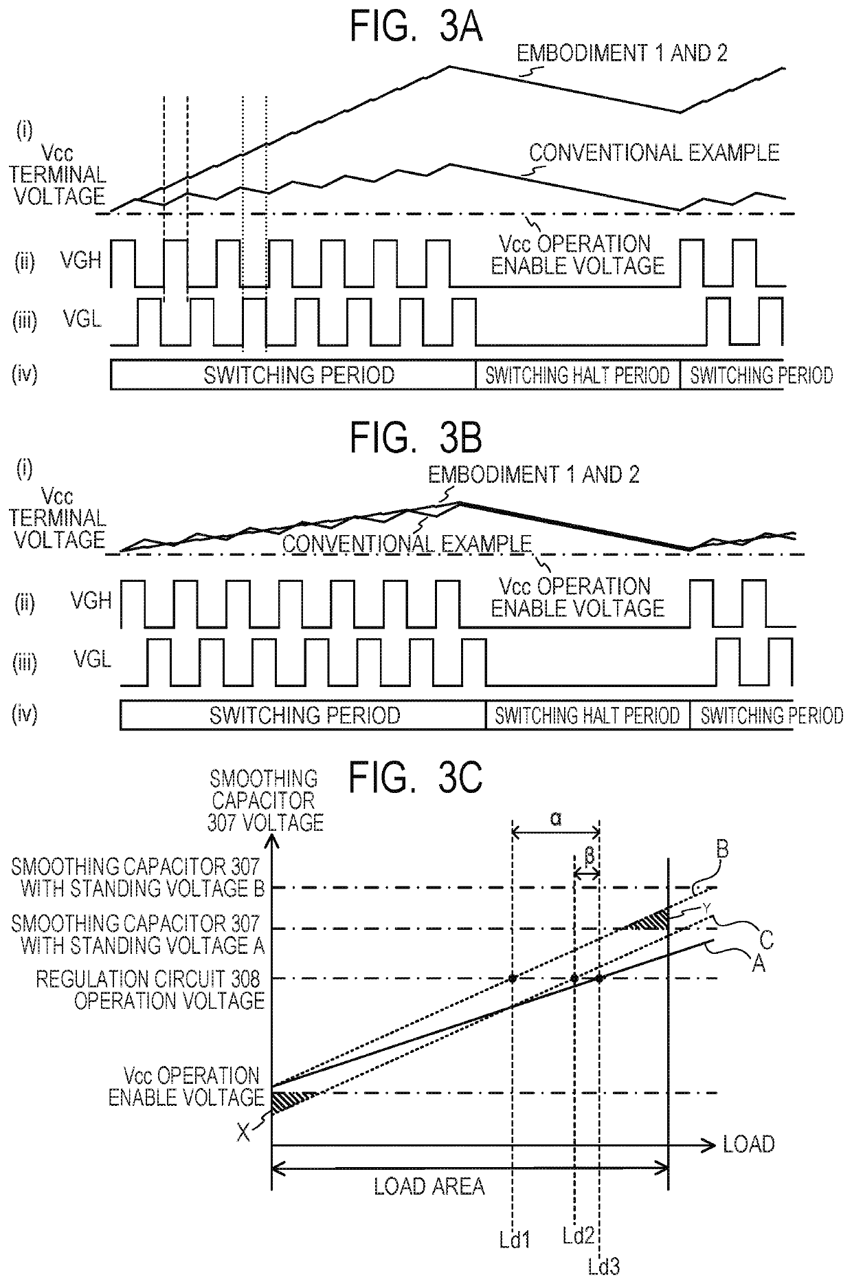
[0076]Thus, in the third embodiment, the circuit is configured such that the voltage supply from the auxiliary winding 302 to the Vcc terminal is cut off if the CPU 502 turns on the FET 604 to increase the DC voltage Vo. By cutting off the voltage supply from the auxiliary winding 302 to the Vcc terminal, the increase rate of the voltage in the smoothing capacitor 307 with respect to the load 204 is further reduced (the gradient of a graph corresponding to the solid line A in FIG. 3C is further reduced). Therefore, compared with the case where the voltage supply from the auxiliary winding 302 to the Vcc terminal is not cut off, the start of operation of the regulation circuit 308 can be further delayed.

[0077]With the above configuration, the withstanding voltage of the components of the auxiliary-winding power supply circuit (for example, the smoothing capacitor 307) under heavy load can be reduced, which leads to a reduced cost and a reduced substrate area. In addition, because the...


PUM


Abstract

The power supply apparatus having two switching elements connected to a primary winding of a transformer includes an adjustment unit for adjusting a voltage and supplying the voltage to a control unit. This voltage results from application of a voltage induced in an auxiliary winding while current is flowing in a predetermined direction with respect to the auxiliary winding as a result of the first switching element turned on and the second switching element turned off, and a voltage induced in the auxiliary winding while current is flowing in the direction opposite to the predetermined direction with respect to the auxiliary winding as a result of the first switching element turned off and the second switching element turned on.

Description

BACKGROUND OF THE INVENTIONField of the Invention[0001]The present invention relates to a power supply apparatus and an image forming apparatus, and in particular relates to a power supply apparatus in which an output voltage from an auxiliary winding of a transformer in a current-resonant converter is supplied to a power supply control IC.Description of the Related Art[0002]A power supply apparatus based on current resonance (hereinafter referred to as a current-resonant converter) is a type of power supply apparatus in which a voltage input from a commercial AC power supply via a diode bridge is switched with switching elements to output a stable DC voltage via an insulating transformer. A Vcc terminal, which is an input terminal, of a power supply control IC typically receives supply of a voltage resulting from rectifying and smoothing an output voltage from an auxiliary winding wound around the transformer of the current-resonant converter. The number of turns of the auxiliary w...

Claims


Application Information

Patent Timeline
Patent Type & Authority Patents(United States)
IPC IPC(8): H02M3/335G03G15/01G03G15/06H02M3/337
CPCH02M3/33592G03G15/0121G03G15/06G03G15/0189H02M3/33523H02M3/3376G03G15/5004G03G15/80Y02B70/10H02M1/0006H02M3/33571H02M3/01
Inventor ODATE, TAKASHIKOJIMA, KEIZOOHNO, ATSUSHI
Owner CANON KK
Why Eureka
Try Eureka