Pilot and burner system for firefighting training

a burner system and pilot technology, applied in the direction of lighting and heating equipment, combustion types, instruments, etc., can solve the problems of affecting compliance with legal, regulatory, and/or administrative training requirements, requiring several hours of labor plus travel costs, and requiring a relatively expensive procedure for the training facility, so as to reduce the cost of disassembly of the electrical infrastructure of the device on site, and adversely affecting complian

Active Publication Date: 2020-02-25
FIREBLAST GLOBAL INC
View PDF21 Cites 4 Cited by
  • Summary
  • Abstract
  • Description
  • Claims
  • Application Information

AI Technical Summary

Benefits of technology

Downtime for maintenance, service, and / or repair of these pilot and burner apparatuses can interfere with operation of training facilities, potentially adversely affecting compliance with legal, regulatory, and / or administrative training requirements. In typical pilot and burner systems, the pilot and burner system would have to be completely removed along with its components from a flame device for maintenance, service, and / or repair. Such a procedure may require a field service technician to travel to the training location and to completely disassemble the piping and electrical infrastructure of the device on site. This may take several hours of labor plus travel costs, making it a relatively expensive procedure for the training facility. Additionally, if specific parts were needed to repair the pilot and burner systems, additional cost may be accrued for a return visit once parts were acquired. Furthermore, the capabilities of the training facility may be reduced during the period in which the pilot and burner system is being repaired. In addition, typical pilot and burner systems may be custom designed for the facilities where they are installed meaning that they are unique to the facility and not necessarily interchangeable with other pilot and burner systems. This can increase the cost of installation as well as costs for maintenance, repair, and / or replacement.
Typical pilot and burner systems include control and fuel lines for the pilot system that are separate from control and fuel lines for the burner system. Because the fuel source and / or control systems are typically located remotely from the pilot and burner system, this can mean that multiple fuel lines and / or electrical lines are installed between the fuel source and the control systems. In some installations, fire training structures or burn props are modified to accommodate these lines so that the lines are not exposed to the harsh conditions in the training scenarios. This can increase the complexity and cost of installation of such pilot and burner systems.
Accordingly, the present disclosure provides for a pilot and burner apparatus that is integrated into a single serviceable unit. The disclosed pilot and burner apparatus is configured to allow the apparatus to be removed by unplugging an electrical disconnection device, disconnecting mechanical connectors, and removing a connection with a fuel source. The apparatus, including valves, electrical components, ignition components, and pilot components, can be removed relatively efficiently (e.g., by removing relatively few connections or fasteners, without the use of tools, in less than 10 minutes, etc.) and either repaired locally on a table or sent back to the manufacture for repairs. In some instances, the apparatus can be replaced by an identical apparatus because the apparatuses are interchangeable rather than being custom-designed for the particular training facility. The pilot and burner apparatus can be a single, compact apparatus that incorporates a pilot system and a burner system with associated controls. The pilot and burner apparatus can be a compact apparatus, fitting within an envelope of about 18 inches by about 12 inches by about 10 inches, an envelope of less than or equal to about 18 inches cubed (18 in. by 18 in. by 18 in.), an envelope of less than or equal to about 20 inches cubed, an envelope of less than or equal to about 22 inches cubed, an envelope at least about 10 inches cubed and / or less than or equal to about 24 inches cubed, or an envelope at least about 12 inches cubed and / or less than or equal to about 18 inches cubed. The pilot and burner apparatus can be configured to be installed and removed by an individual. This can be due at least in part to the compact envelope of the apparatus as well as the weight of the apparatus (e.g., at least 25 pounds and / or less than or equal to about 50 pounds, at least about 30 pounds and / or less than or equal to about 45 pounds, or at least about 35 pounds and / or less than or equal to about 40 pounds).
The disclosed apparatus can reduce the cost of repairs for a training facility by reducing travel cost associated with repairs of the apparatus as well as costs for disassembling and reassembling the apparatus. The disclosed apparatus may also allow for the training facility to have an inventory of compatible apparatuses in stock that allow for an efficient exchange of components, allowing a unit to be sent off for maintenance while installing the interchangeable unit in the facility. This can reduce downtime of the training facility or training structure. The disclosed apparatus can also reduce the time and cost associated with manufacturing pilot and burner apparatuses for training facilities due at least in part to their interchangeability.
In addition, the present disclosure provides for an integrated pilot and burner apparatus that utilizes a single fuel line to provide fuel to both the pilot system and the burner system. The disclosed pilot and burner apparatus can be controlled using a local or remote burn control system that can operate the apparatus in a pilot phase to generate a pilot flame, and in a burn phase to provide a controlled flame to a training structure. This design can reduce the complexity and cost associated with operation, installation, maintenance, and repair of the pilot and burner apparatus. The integrated pilot and burner apparatus can be a single, compact apparatus that is easily installed and / or removed in intended structures or facilities.

Problems solved by technology

Downtime for maintenance, service, and / or repair of these pilot and burner apparatuses can interfere with operation of training facilities, potentially adversely affecting compliance with legal, regulatory, and / or administrative training requirements.
This may take several hours of labor plus travel costs, making it a relatively expensive procedure for the training facility.
Additionally, if specific parts were needed to repair the pilot and burner systems, additional cost may be accrued for a return visit once parts were acquired.
Furthermore, the capabilities of the training facility may be reduced during the period in which the pilot and burner system is being repaired.
In addition, typical pilot and burner systems may be custom designed for the facilities where they are installed meaning that they are unique to the facility and not necessarily interchangeable with other pilot and burner systems.
This can increase the cost of installation as well as costs for maintenance, repair, and / or replacement.
This can increase the complexity and cost of installation of such pilot and burner systems.

Method used


Image

  • Pilot and burner system for firefighting training
  • Pilot and burner system for firefighting training
  • Pilot and burner system for firefighting training

Examples


example pilot

and Burner System

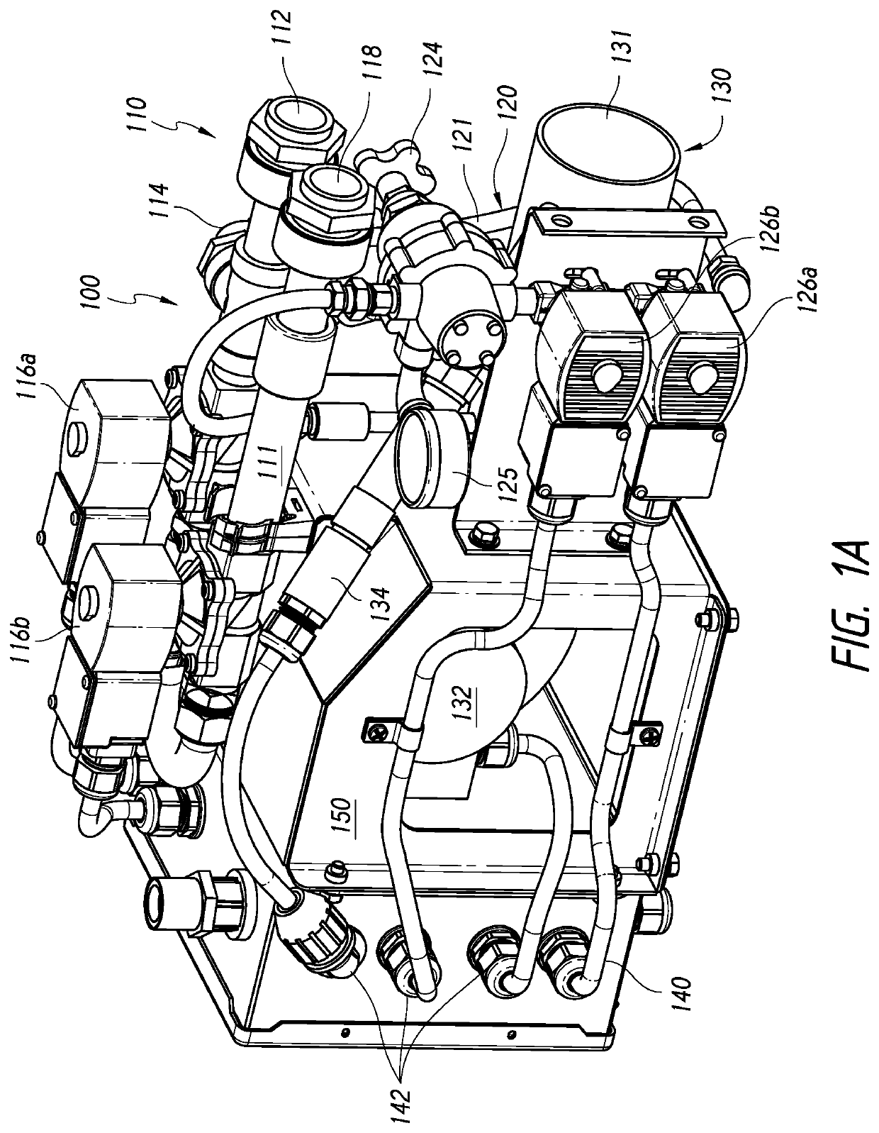
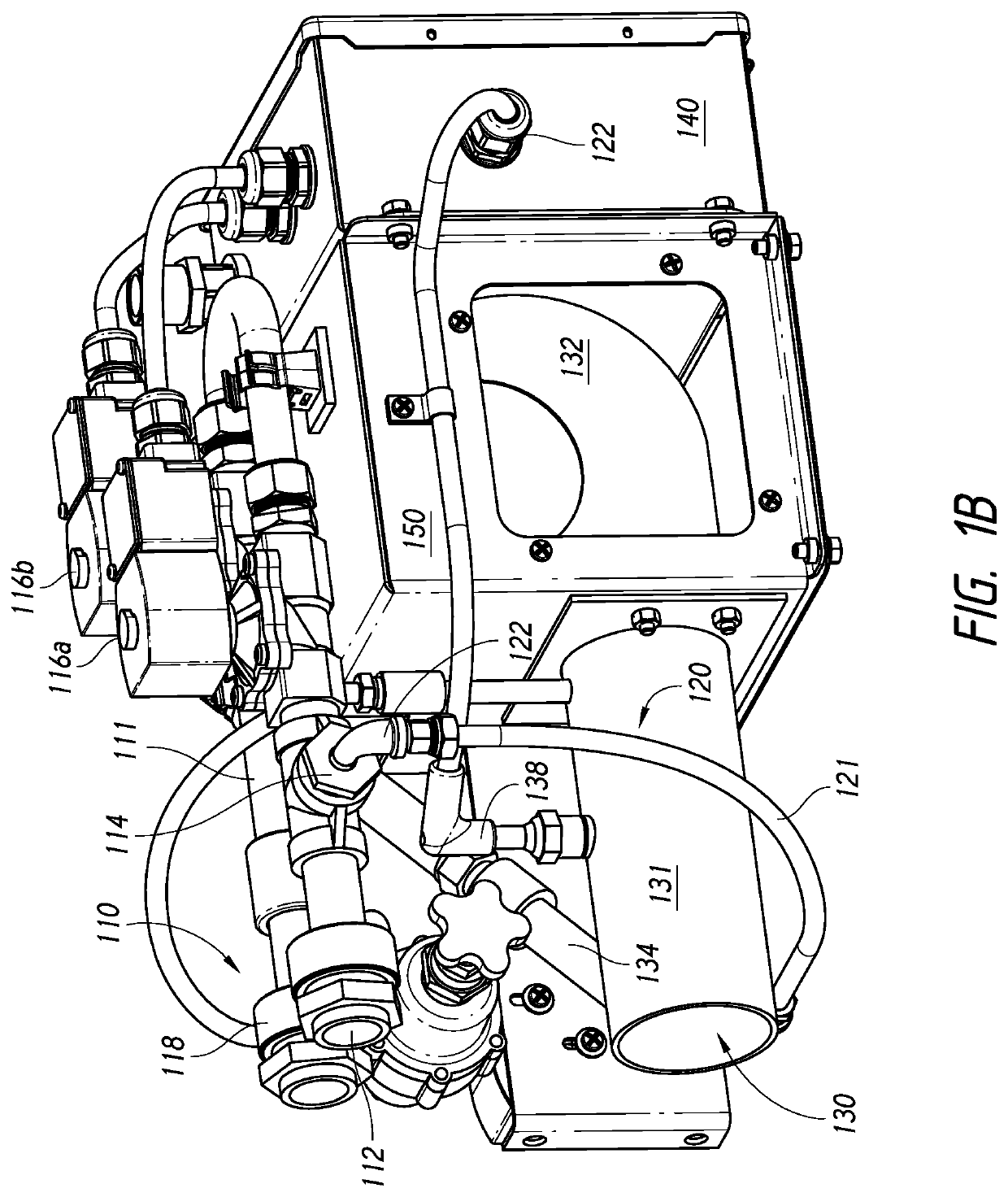
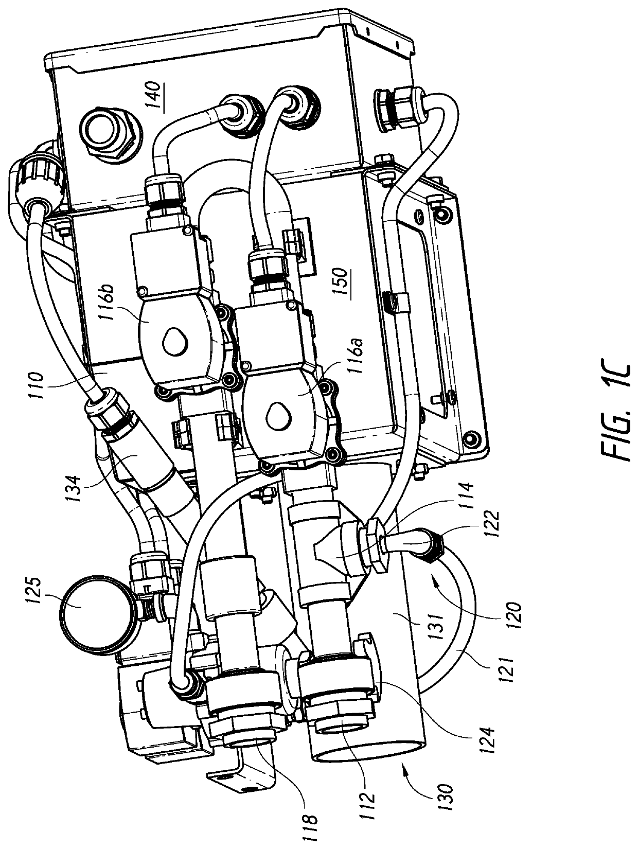
FIG. 2 illustrates a functional block diagram of an example pilot and burner system 202 including a pilot and burner apparatus 200 and a flame control system 260. The pilot and burner apparatus 200 can be similar to any of the pilot and burner apparatuses described herein with reference to FIGS. 1, 4, and 5. The pilot and burner apparatus 200 can be configured to be communicably coupled to the flame control system 260. The flame control system 260 can be configured to control components of the pilot and burner apparatus 200 to light a pilot flame, to control the flow of fuel to a burn prop through fuel pipe 284, to control the pilot flame delivered through a main burner pipe 282, and / or to control attributes of the fire produced by the pilot and burner apparatus 200. Attributes of the fire produced can include, but are not limited to, flame shape, flame height, flame volume, burn rate, visual effects, and combinations thereof. In some implementations, the attributes...

embodiment 1

2. The integrated pilot and burner apparatus of Embodiment 1 further comprising a pilot regulator coupled to the pilot fuel conduit, the pilot regulator configured to regulate a fuel pressure in the pilot fuel conduit.

3. The integrated pilot and burner apparatus of any of Embodiments 1-2, wherein the integrated pilot and burner apparatus weighs less than or equal to 50 pounds.

4. The integrated pilot and burner apparatus of any of Embodiments 1-3 further comprising a secondary main fuel valve positioned between the main fuel valve and the main fuel outlet.

5. The integrated pilot and burner apparatus of any of Embodiments 1-4 further comprising a secondary pilot fuel valve positioned between the pilot fuel valve and the pilot fuel outlet.

6. The integrated pilot and burner apparatus of any of Embodiments 1-5, wherein the ignition component comprises:an ignition coil; anda flame igniter,wherein the ignition coil is electrically coupled to the flame igniter, andwherein the flame igniter ...

embodiment 7

8. The integrated pilot and burner apparatus of Embodiment 7, wherein the optical sensor comprises an ultraviolet sensor configured to generate electrical signals corresponding to levels of ultraviolet radiation within the pilot flame tube.

9. The integrated pilot and burner apparatus of any of Embodiments 1-8 further comprising a support structure configured to couple to one or more of the pilot flame tube, the main fuel conduit, and the pilot fuel conduit.


PUM


Abstract

A pilot and burner apparatus is provided for use in firefighting training. The apparatus includes a main fuel conduit and a main fuel valve. The apparatus includes a pilot tube and a pilot fuel conduit configured to deliver fuel from the main fuel conduit to the pilot tube. The apparatus includes main and pilot fuel valves to respectively control a flow of fuel in the main and pilot fuel conduits. In a pilot phase, the valves direct fuel to the pilot tube. An ignition component is configured to ignite fuel in the pilot tube to generate a pilot flame. In a burn phase, the pilot flame generates a controllable flame out of a main burner pipe by igniting fuel exiting the main fuel conduit. The controllable flame can be delivered to a training structure for training purposes.

Description

BACKGROUNDFieldThe present disclosure relates to apparatuses and systems for providing controlled fires for training individuals in extinguishing fires, and in particular, apparatuses and systems that include an integrated pilot and burner system.Description of Related ArtWhen training firefighters, law enforcement, port authorities, first responders, military and the like, an apparatus can be used to create simulated fire conditions to permit trainees to practice firefighting techniques. Different scenarios can be created for firefighting training through the use of such an apparatus in combination with a variety of training structures (e.g., fire props or burn props) and / or in a variety of environments (e.g., within a building, in the open, on or around a vehicle, etc.). The simulated fire conditions can be built and designed with a variety of scenarios trainees will likely face in the field. For example, simulated scenarios can include attic fires, hidden fires in dropped ceiling...

Claims


Application Information

Patent Timeline
Patent Type & Authority Patents(United States)
IPC IPC(8): G09B9/00F23Q9/00F23D99/00G09B19/00
CPCF23D91/00G09B19/00G09B9/00F23Q9/00G09B25/00A62C99/0081
Inventor EGELIN, JR., RICHARD WAYNEYIRSA, CHRISTOPHER CHARLES
Owner FIREBLAST GLOBAL INC
Why Eureka
Try Eureka