Electric brake system

a technology of brake system and electric brake, which is applied in the direction of brake system, process and machine control, instruments, etc., can solve the problems of increased braking distance or deterioration of brake feeling, uncomfortable driving of drivers or the like, etc., to improve safety, reduce operation sound and power consumption, and improve safety.

Active Publication Date: 2020-03-03
NTN CORP
View PDF26 Cites 0 Cited by
  • Summary
  • Abstract
  • Description
  • Claims
  • Application Information

AI Technical Summary

Benefits of technology

[0008]An object of the present invention is to provide an electric brake system that changes responsiveness depending on responsiveness required for an electric brake device, thereby enabling operation sound and power consumption to be reduced without influencing movement of a vehicle.
[0012]According to the above configuration, the response requirement determination module 14 determines the responsiveness required for the brake actuator 4, from one or both of the braking requirement and the information about the travelling condition of the vehicle. The control modification module 15 changes the control operation formula to be used for the follow-up control by the control operation module 12, depending on the responsiveness determined by the response requirement determination module 14. Therefore, it is possible to control changing the responsiveness depending on responsiveness required for the electric brake device 3. Thus, operation sound and power consumption are reduced without influencing movement of the vehicle. It is noted that the “brake operation member” is, for example, a brake pedal. In addition, the “vehicle-stable-travelling control system” is, for example, an antilock control system (ABS), an attitude control device, or collision preventing control device. In addition, the “information about a travelling condition of the vehicle” includes the travelling speed, the change rate of the travelling speed (acceleration or deceleration), the turning angle, the steering angle, or the like. The responsiveness determined by the response requirement determination module 14 may be a stepwise value or a continuous value.
[0013]In the present invention, the response requirement determination module 14 may determine responsiveness of the braking force from the target braking force or a control target value obtained from the target braking force. For example, in the case where the degree of change in the target braking force or in a control target value obtained from the target braking force is great, the electric brake device 3 is required to have high responsiveness so as to be able to follow the control target value, in order to improve safety, vehicle behavior, and the like. On the other hand, in the case where the degree of change is small, the electric brake device 3 is required to perform silent operation so as not to give an uncomfortable feeling to a vehicle operator, rather than having responsiveness. Therefore, if the response requirement determination module 14 is configured to determine the responsiveness of the braking force from the target braking force or the control target value obtained from the target braking force, operation sound and power consumption are reduced without influencing movement of the vehicle. It is noted that the control target value obtained from the target braking force is, for example, a voltage value, a current value, a motor rotational position, or the advancement / retraction position of the friction member actuator 33.
[0014]In the present invention, the response requirement determination module 14 may estimate responses of the brake actuator 4, each response being obtained when a corresponding one of a plurality of control operation formulas is applied, the control modification module 15 allowing switchover among the plurality of control operation formulas, compare the plurality of estimation results with each other, and determine the responsiveness of the braking force on the basis of the estimation comparison results. Performing a plurality of estimations for responsiveness and comparing the estimation results with each other as described above makes it possible to more appropriately determine brake responsiveness fulfilling desired silence.
[0015]In the present invention, the response requirement determination module 14 may determine responsiveness of the braking force from at least one of a speed of the vehicle on which the electric brake device 3 is mounted, and a wheel speed thereof. In the case where the speed of the vehicle is fast or the wheel speed is fast, great sound due to travelling occurs at a part other than the brake device 3. On the other hand, in such a case, responsiveness of the braking force is desired to be as fast as possible. Since the response requirement determination module 14 is configured to determine the responsiveness from at least one of the speed of the vehicle and the wheel speed, operation sound and power consumption are reduced more effectively without influencing movement of the vehicle.

Problems solved by technology

Such an electric brake device causes a sound of a different type from those of hydraulic brake devices which are generally prevalent, and is likely to make a driver or the like uncomfortable even if the sound is small.
If the operation sound is reduced, the responsiveness is lowered and this might lead to increase in braking distance or deterioration in brake feeling.

Method used


Image

  • Electric brake system
  • Electric brake system
  • Electric brake system

Examples


Embodiment Construction

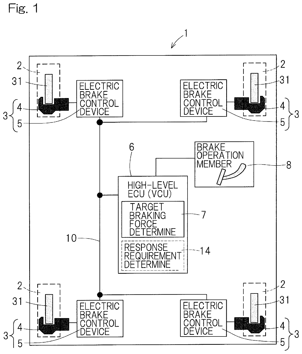
[0031]An embodiment of the present invention will be described with reference to the drawings. FIG. 1 shows an example in which an electric brake system of the present embodiment is used in a vehicle such as an automobile having four wheels. In the vehicle 1, an electric brake device 3 is provided to each of left and right wheels 2 on the front side (upper side in FIG. 1) and the rear side. A travelling driving source (not shown) is an internal combustion engine or an electric motor, or both of them. The electric brake device 3 may be a friction brake device. The electric brake device 3 is composed of a brake actuator 4, which is a mechanistic part, and an electric brake control device 5 for controlling the brake actuator 4. It is noted that the configuration shown in the present embodiment is a configuration needed for implementing the electric brake system proposed by the present inventors, and other functions such as a redundant function may be added appropriately as necessary.

[0...


PUM


Abstract

Provided is an electric brake system that changes responsiveness depending on responsiveness required for an electric brake device, thereby enabling operation sound and power consumption to be reduced without influencing movement of a vehicle. The electric brake system includes one or more electric brake device (3) each having a control operation module (12) for performing follow-up control for a target braking force. The electric brake system includes a response requirement determination module (14) for determining responsiveness required for the brake actuator (4) from one or both of a braking requirement and the vehicle travelling condition. The braking requirement is outputted from a brake operation member or a vehicle-stable-travelling control system. The electric brake system includes a control modification module (15) for changing a control operation formula to be used for follow-up control by the module (12), depending on responsiveness determined by the module (14).

Description

CROSS REFERENCE TO THE RELATED APPLICATION[0001]This application is a continuation application, under 35 U.S.C. § 111(a), of international application No. PCT / JP2016 / 072677, filed Aug. 2, 2016, which claims Convention priority to Japanese patent application No. 2015-158027, filed Aug. 10, 2015, the entire disclosure of which is herein incorporated by reference as a part of this application.BACKGROUND OF THE INVENTIONField of the Invention[0002]The present invention relates to an electric brake system provided to a vehicle such as an automobile.Description of Related Art[0003]Conventionally, an electric brake device that controls a braking force by an electric motor is proposed (for example, Patent Document 1). In addition, an electric actuator using a planetary roller screw mechanism is proposed (for example, Patent Document 2).RELATED DOCUMENTPatent Document[0004][Patent Document 1] JP Laid-open Patent Publication No. H06-327190[0005][Patent Document 2] JP Laid-open Patent Publicat...

Claims


Application Information

Patent Timeline
Patent Type & Authority Patents(United States)
IPC IPC(8): B60T8/72B60T1/06B60K31/02B60T7/22B60T13/66B60T8/1761B60T8/1755F16D65/18B60T8/17B60T13/74F16D65/14B60T7/12F16D55/226B60K31/00
CPCB60T1/065B60T8/17B60T13/662B60T7/22B60T13/74B60T8/1755B60T8/17555B60T8/72B60T8/1761B60T7/12B60T13/741B60K31/02F16D65/183F16D65/18F16D55/226B60Y2400/81B60K2031/0091B60W2720/10B60W2710/182B60Y2300/143B60W2520/10
Inventor MASUDA, YUI
Owner NTN CORP
Why Eureka
Try Eureka