High brightness short-wavelength radiation source (variants)

a radiation source and short-wavelength technology, applied in the direction of x-ray tube target materials, electrical discharge tubes, electrical apparatus, etc., can solve the problems of complicating the overall design reducing the service life of the radiation source, so as to improve the service life and reduce the operating cost. , the effect of improving the service li

Active Publication Date: 2020-03-10
ISTEQ BV +1
View PDF1 Cites 6 Cited by
  • Summary
  • Abstract
  • Description
  • Claims
  • Application Information

AI Technical Summary

Benefits of technology

[0024]In a preferred embodiment of the invention, the rotating target assembly is a disk with a peripheral part in a form of a ring barrier, on an inner surface of which, facing the axis of rotation, there is the annular groove with a surface profile preventing a release of the target material in a radial direction and in both directions along the axis of rotation.
[0037]In the embodiment of the invention, a laser pulse repetition rate is high enough to provide high-efficient evaporation of microdroplet fractions of debris particles of the previous pulse by both short-wavelength radiation and fluxes of laser-produced plasma.
[0044]The technical result of the invention is the creation of X-ray and VUV radiation sources of high brightness with mitigation of the debris particles on the path of the passing beam of the short-wavelength radiation, characterized by increased service life, ease of operation and lower operating costs.

Problems solved by technology

Thus, the control of lithographic mask defect-free production and operation is one of the key problems of lithography, and the creation of a device for the diagnosis of lithographic masks and its key element, the high-brightness actinic source, is one of the priorities of the development of EUV lithography.
Therefore, their usage for mask inspection is inadequate due to the excessive complexity and cost.
However, the circulation system of the jet liquid metal target is quite complex, which complicates the overall design of the radiation source.
Also, these sources of radiation are characterized by the problem of contamination of the exit window, through which the beam of short-wavelength radiation is released.
Part of this disadvantage is ameliorated in the high brightness liquid-metal jet X-ray source known from the U.S. Pat. No. 8,681,943, issued Mar. 25, 2014, in which an X-ray beam leaves the vacuum chamber through an exit window (preferably made of beryllium foil), equipped with a protective film element with a system of evaporative cleaning.
However, the temperatures required for evaporative cleaning are high, e.g. about 1000° C. and more, for evaporation of Ga and In, which complicates the device.
However, these methods do not provide highly effective suppression of the microdroplet fractions of debris particles in the path of the short-wavelength radiation beam.
This limits the uptime of the equipment, in which the radiation source is affected due to the contamination of its optical elements.
However, the complexity of using these debris-mitigation techniques in a compact radiation source means that technically they are too difficult to implement.
However, the use of a CNT-membrane for trapping debris particles generated by EUV lithography source is unlikely, as the CNT-membrane is highly likely to be destroyed by such powerful radiation.
For less powerful sources of radiation, there is also a limitation.
As our research has shown, a small fraction of debris particles with microdroplet sizes of more than 300 nm can penetrate through the CNT-membrane, which does not ensure the purity of the short-wavelength radiation source only through the use of a CNT-membrane.

Method used


Image

  • High brightness short-wavelength radiation source (variants)
  • High brightness short-wavelength radiation source (variants)
  • High brightness short-wavelength radiation source (variants)

Examples


Embodiment Construction

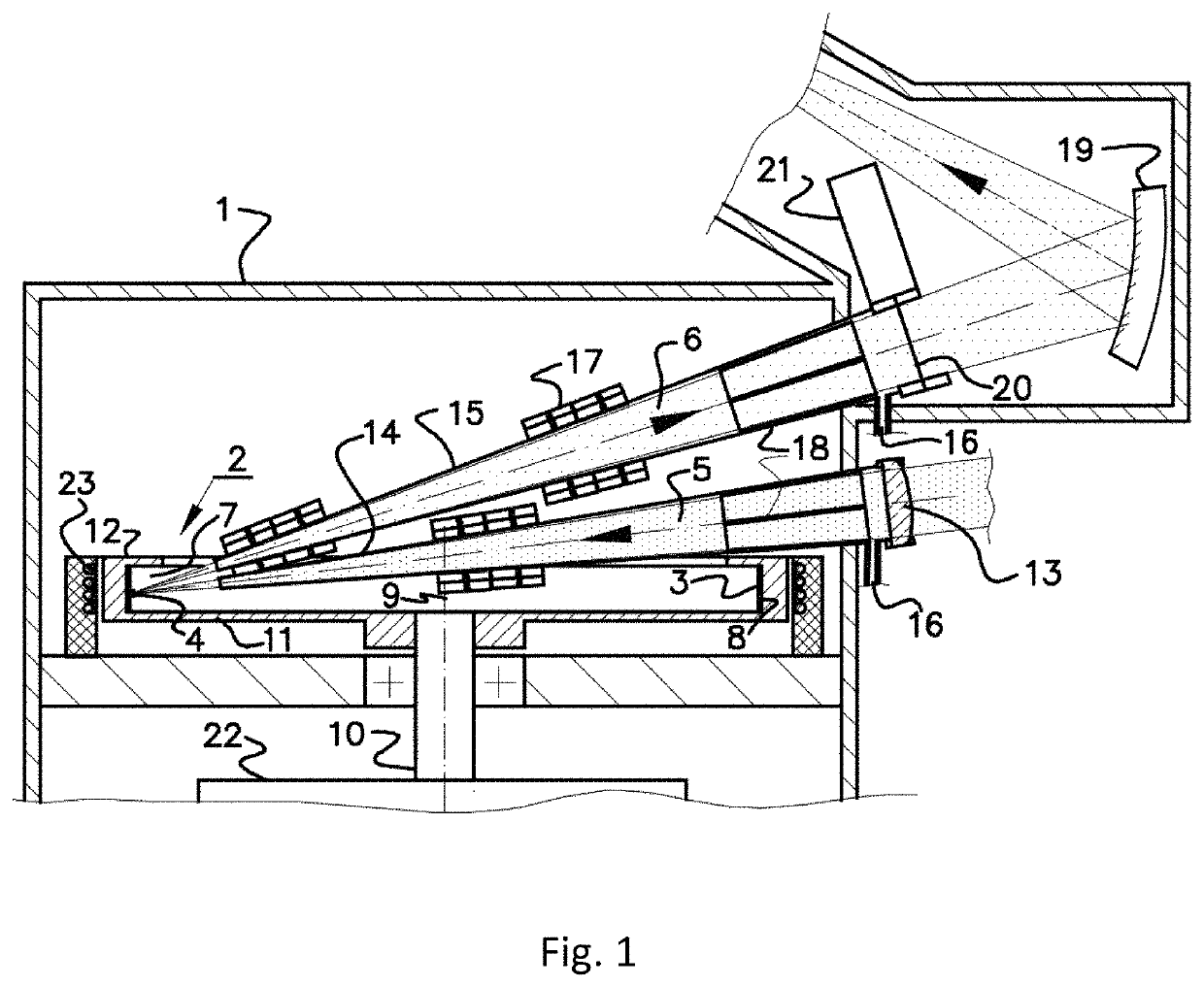
[0059]In accordance with the example of the invention shown in FIG. 1, a high brightness source of short-wavelength radiation contains: a vacuum chamber 1 with a rotating target assembly 2, supplying target 3 in the interaction zone 4. In the vacuum chamber 1, an energy beam 5 is focused on the target in the interaction zone 4. The short-wavelength radiation generated in the interaction zone 4, intended for use, leaves the interaction zone 4 in the form of a useful beam of short-wavelength radiation 6. Rotating target assembly 2 is made with an annular groove 7, and target 3 is a layer of molten metal formed by centrifugal force on the surface 8 of the annular groove, facing the axis of rotation 9. The energy beam 5 is either an electron beam or a pulsed laser beam. For simplification, the energy source emitting the energy beam 5 on FIG. 1 is not shown.

[0060]At a sufficiently large centrifugal force, the surface of the liquid metal target 3 is parallel to the axis of rotation 9 and ...


PUM

PropertyMeasurementUnit
linear velocityaaaaaaaaaa
wavelength rangeaaaaaaaaaa
transparencyaaaaaaaaaa

Abstract

High-brightness short-wavelength radiation source contains a vacuum chamber with a rotating target assembly having an annular groove, an energy beam focused on the target, a useful short-wavelength radiation beam coming out of the interaction zone, wherein the target is a layer of molten metal formed by a centrifugal force on a surface of the annular groove facing a rotation axis. A replaceable membrane made of carbon nanotubes may be installed on a pathway of the short-wavelength radiation beam for debris mitigation. In the embodiments of the invention the energy beam is a pulsed laser beam. The pulsed laser beam may consist of pre-pulse and main-pulse, with parameters such as laser pulse repetition rate chosen in order to suppress debris. In other embodiments the energy beam is the electron beam produced by an electron gun and the rotating target assembly is a rotating anode.

Description

CROSS-REFERENCE TO RELATED APPLICATIONS[0001]Current patent application claims priority to the Russian patent application RU2019113052 filed on Apr. 26, 2019 and is a continuation in part of U.S. patent application Ser. No. 16 / 103,243 filed on Aug. 14, 2018, all of which incorporates herein by reference in their entirety.FIELD OF INVENTION[0002]The invention refers to high brightness radiation sources designed to generate X-ray and vacuum ultraviolet (VUV) radiation at wavelengths of approximately 0.01 to 200 nm, which provide highly effective debris mitigation in the path of the short-wavelength beam to ensure the long-term operation of the radiation source and its integrated equipment. Applications include X-ray and VUV metrology, microscopy, X-ray material diagnostics, biomedical and medical diagnostics, and various types of controls, including inspection of lithographic EUV masks.BACKGROUND OF INVENTION[0003]High-intensity X-ray and VUV sources are used in many fields: microscop...

Claims


Application Information

Patent Timeline
Patent Type & Authority Patents(United States)
IPC IPC(8): H05G2/00
CPCH05G2/008H05G2/005H05G2/006H01J2235/082H01J35/10H01J35/02
Inventor VINOKHODOV, ALEKSANDR YURIEVICHIVANOV, VLADIMIR VITALIEVICHKOSHELEV, KONSTANTIN NIKOLAEVICHKRIVOKORYTOV, MIKHAIL SERGEYEVICHKRIVTSUN, VLADIMIR MIKHAILOVICHLASH, ALEKSANDR ANDREEVICHMEDVEDEV, VYACHESLAV VALERIEVICHSIDELNIKOV, YURY VIKTOROVICHYAKUSHEV, OLEG FELIKSOVICHKHRISTOFOROV, OLEG BORISOVICHGLUSHKOV, DENIS ALEKSANDROVICHELLWI, SAMIR
Owner ISTEQ BV
Why Eureka
Try Eureka