Flight vehicle air breathing propulsion system with isolator having obstruction

a propulsion system and air breathing technology, applied in the direction of combustion air/fuel air treatment, machines/engines, transportation and packaging, etc., can solve the problems of high distortion of flow profile, reduce combustion efficiency, and inlet start, so as to increase the vortex strength, reduce the effect of energy flow and strong fuel/air mixing

Active Publication Date: 2020-03-17
RAYTHEON CO
View PDF24 Cites 2 Cited by
  • Summary
  • Abstract
  • Description
  • Claims
  • Application Information

AI Technical Summary

Benefits of technology

[0006]A flight vehicle engine isolator or diffuser has an obstruction that increases mixing of the flow along the obstruction length all the way to the isolator exit.
[0007]A flight vehicle engine isolator or diffuser has an obstruction that increases vortex strength that may help further mix the low energy flow as well as provide stronger fuel / air mixing downstream in the combustor.
[0008]A flight vehicle engine isolator or diffuser has an obstruction that reduces flow separations and / or recirculations and low momentum flow regions.
[0009]A flight vehicle engine isolator or diffuser has an obstruction that improves isolator exit flow profile consistency and, if desired, uniformity across multiple flight conditions (Mach number, altitude, angle of attack, sideslip angle) and / or throttle (back pressure) settings.
[0010]A flight vehicle engine isolator or diffuser has an obstruction that increases maximum back pressure capability of the isolator by providing high shear stress regions for shock anchoring, by decreasing losses due to separations, and by removing the worst potential flow separation on the body-side centerline which occurs from engine demanded pressure rises that creates strong shock wave boundary layer interactions / separations.
[0011]A flight vehicle engine isolator or diffuser has an obstruction that helps anchor one or more shocks in the isolator.

Problems solved by technology

This pressure rise must not allow pressure communications to travel through the isolator boundary layer and upstream past the inlet throat or allow the shock train to extend upstream of the inlet throat, both potentially resulting in unstart of the inlet.
These strong shock interactions with weak boundary layers can result in high distortion of the flow profile (mass flux, Mach Number, total pressure, etc.) at the isolator exit, which will be ingested by the engine and may reduce combustion efficiency or cause engine stall / flame-out.

Method used


Image

  • Flight vehicle air breathing propulsion system with isolator having obstruction
  • Flight vehicle air breathing propulsion system with isolator having obstruction
  • Flight vehicle air breathing propulsion system with isolator having obstruction

Examples


Embodiment Construction

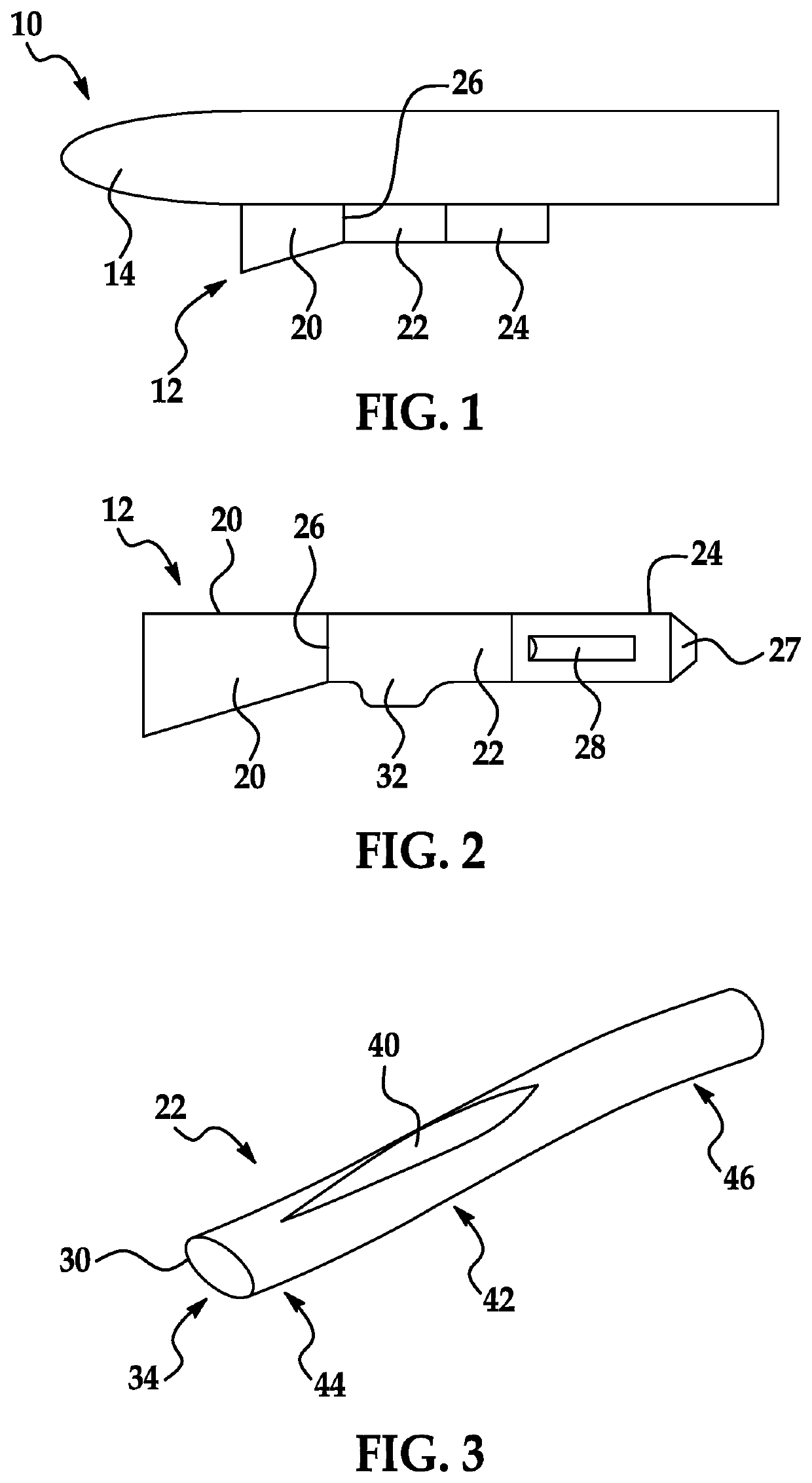
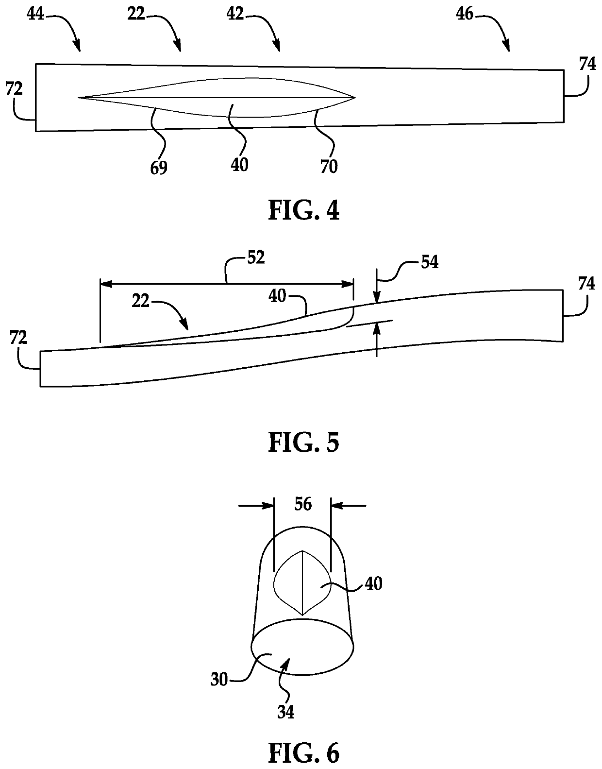
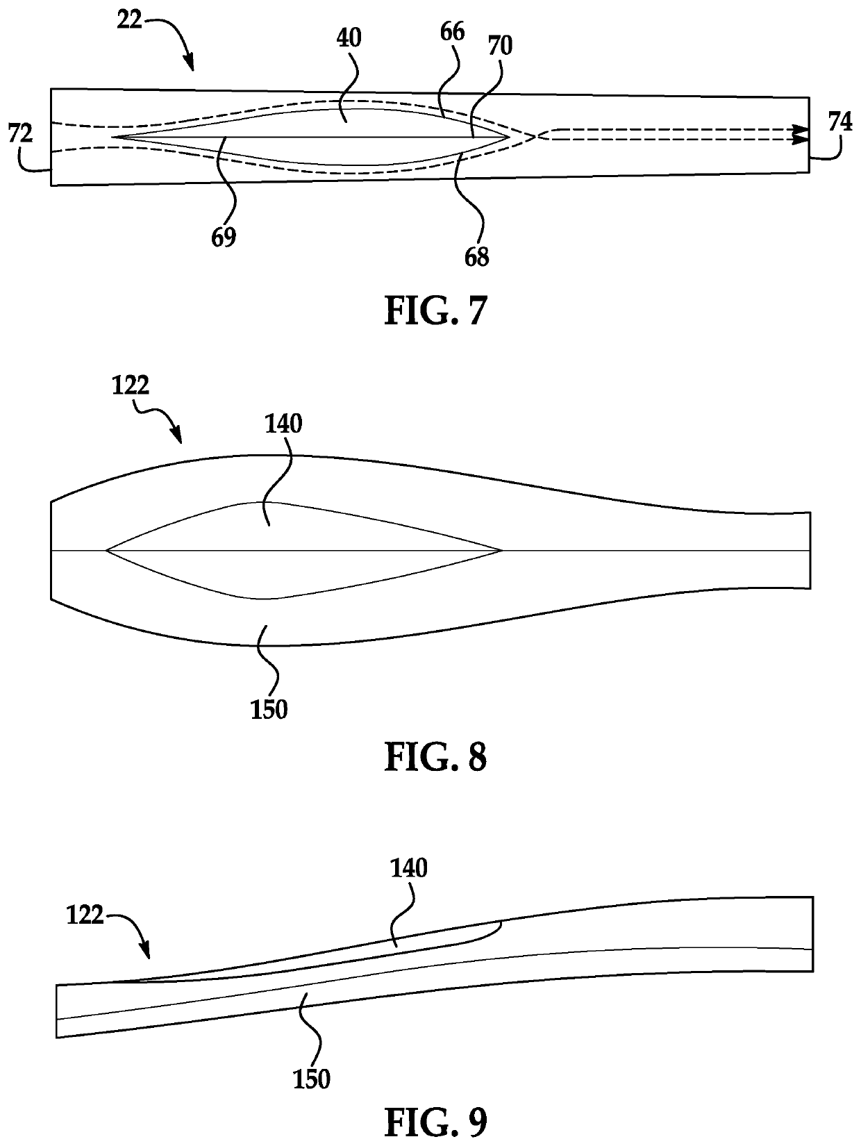
[0055]A flight vehicle has a propulsion system that includes air inlet, an isolator (or diffuser) downstream of the air inlet, and a combustor downstream of the isolator. The isolator includes an obstruction that protrudes inwardly from an inner wall of the isolator, into the flow channel in which air flows through the isolator, from the air inlet to the combustor. The obstruction may be oriented in a longitudinal direction along which flow passes through the isolator, and has a height that is greater than several boundary layer thicknesses of the flow. The obstruction, when placed in regions of low energy / low momentum flow does not allow this flow-state to setup but diverts the flow to either side of it, in a direction perpendicular to the longitudinal direction through the isolator, for example in a radial direction in a round cross-section isolator. During diversion the low energy flow compresses and starts to mix with higher energy flow adjacent to it quickly as it traverses the...


PUM


Abstract

A flight vehicle has a propulsion system that includes an air inlet, an isolator (or diffuser) downstream of the air inlet, and a combustor downstream of the isolator. The isolator includes an obstruction that protrudes inwardly from an inner wall of the isolator, into the flow channel in which air flows through the isolator. The obstruction diverts the flow to either side of it. Downstream of the obstruction the flow on either side of the obstruction comes together again, leading to mixing of the flow, for example including mixing of low energy and boundary layer flow with high energy flow. This mixing of flow may make for a more uniform flow at the exit of the isolator. In addition the obstruction may help fix the location of shocks within the isolator, providing longer flow mixing length in the isolator.

Description

FIELD OF THE INVENTION[0001]The invention is in the field of propulsion systems for flight vehicles such as airplanes, missiles, pulse detonation engines, projectiles or access-to-space systems.DESCRIPTION OF THE RELATED ART[0002]Supersonic and hypersonic airbreathing engines, such as dual-mode ramjets / scramjets, include isolators. The isolator is typically a constant-area or slightly-monotonically-increasing area section located downstream of an air inlet throat, between the inlet and an engine / combustor. The purposes for the isolator may be to separate fluctuations between conditions in the inlet and the combustor, to provide a desired flow profile to the combustor, to reduce problems with inlet unstart and / or combustion stability. The isolator may also provide additional pressure rise upstream of the combustor, in the isolator, when the combustor demands it. The isolator must efficiently execute the above at all required flight conditions and throttle settings the air vehicle wil...

Claims


Application Information

Patent Timeline
Patent Type & Authority Patents(United States)
IPC IPC(8): F02K7/10F02C3/04B64C23/04B64C30/00F02C7/04B64D27/16B64D33/02
CPCB64D33/02B64C23/04B64D27/16F02C7/04F02K7/10F02C3/04B64C30/00B64D2033/026B64D2033/0226F05D2240/35F05D2250/72F05D2250/73F05D2220/10F05D2220/80
Inventor CICCHINI, NICHOLAS P.
Owner RAYTHEON CO
Why Eureka
Try Eureka