Matrix converter operating in current control mode using feed forward signals

a matrix converter and current control technology, applied in the field of matrix converters, can solve the problems of matrix converters that cannot be controlled to provide short circuits between input phase lines without risking damage to switching elements, matrix converters that cannot provide output voltages that are greater, etc., to minimize the possibility of pwm controller saturation and increase energy

Active Publication Date: 2020-03-17
HAMILTON SUNDSTRAND CORP
View PDF7 Cites 6 Cited by
  • Summary
  • Abstract
  • Description
  • Claims
  • Application Information

AI Technical Summary

Benefits of technology

[0021]In accordance with still another aspect of the disclosure, a matrix converter system having a current control mode operation is provided. The system includes a matrix converter having a switching matrix, the matrix converter being coupled at its low-voltage side to a generator and coupled at its output load side to a load. A controller having a pulse width modulation (PWM) controller is configured to control matrix converter via its switching matrix to increase energy within internal inductances of the generator when a short circuit occurs in the switching matrix. A feed forward calculator is configured to calculate feed forward values of active and reactive current. The feed forward values of the active and reactive current are calculated based on power demand at the output of the matrix converter. The feed forward values of the active and reactive current are used to adjust currents that affect input to the controller to minimize the possibility of saturation of the PWM controller.

Problems solved by technology

These capacitors create low impedance paths between phases and thus, the matrix converter cannot be controlled to provide short circuits between input phase lines without risking damage to the switching elements.
Since the matrix converter cannot create output voltages higher than the line-to-line input voltages, the matrix converter's ability to provide output voltage without distortion is limited.
Specifically, the matrix converter is not able to provide an output voltage that is greater than 86.6% of the input voltage without distortion.

Method used


Image

  • Matrix converter operating in current control mode using feed forward signals
  • Matrix converter operating in current control mode using feed forward signals
  • Matrix converter operating in current control mode using feed forward signals

Examples


Embodiment Construction

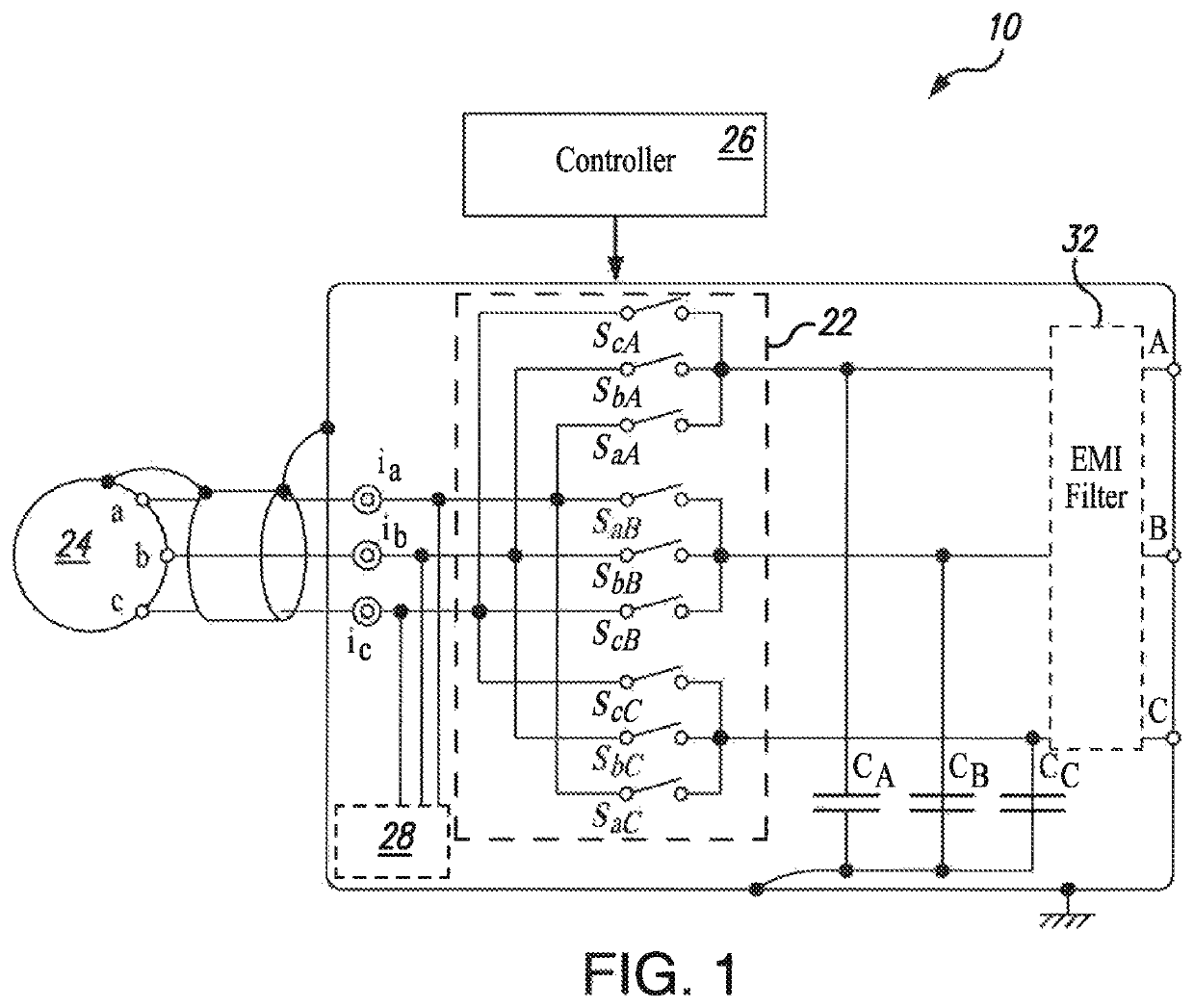
[0044]A matrix converter system is disclosed herein that operates from a controllable voltage source in a current control mode (CCM). The matrix converter system includes a matrix converter and a controller configured to control the matrix converter. The controller is configured to calculate a feed forward output phase angle, the feed forward output phase angle being an estimation of an angle between current and voltage output by the matrix converter. The angular position of the voltage output by the matrix converter is adjusted as a function of the feed forward output phase angle output voltage with desired phase angle or position.

[0045]In embodiments, the feed forward calculator can be further configured to calculate feed forward values of active and reactive currents with respect to back electromotive frequency (EMF) of the generator. The feed forward values of the active and reactive current can be used to adjust currents that affect the controller to minimize the possibility of...


PUM


Abstract

A matrix converter system having a current control mode operation is provided. The system includes a matrix converter having a switching matrix. The matrix converter is coupled at its low-voltage side to a generator and at its output load side to a load. A controller having a pulse width modulation (PWM) control circuit is configured to control the matrix converter via its switching matrix to increase energy within the internal inductances of the generator when the switching matrix causes a short circuit. A feed forward calculator is configured to calculate a feed forward output phase angle. The feed forward output phase angle is an estimation of an angle between an output current vector and an output voltage vector that represent feedback signals of current and voltage output by the matrix converter. The angular position of the voltage output vector is adjusted as a function of the feed forward output phase angle to align angular position or phase angle of the voltage output vector that represents the voltage output with a selected angular position or phase angle.

Description

STATEMENT REGARDING FEDERALLY SPONSORED RESEARCH OR DEVELOPMENT[0001]This invention was made with government support under contract number DE-AR00000891, under the ARPA-E FOA Circuits Program, titled Power Conversion Through Novel Current Source Matrix Converter, awarded by the U.S. Department of Energy, April 2018. The government has certain rights in the invention.BACKGROUND1. Field of the Disclosure[0002]The present disclosure relates to a matrix converter, and more particularly, to a matrix converter operating in current control mode using feed forward signals.2. Description of Related Art[0003]Matrix converters are generally used as alternating current (AC)-to-AC converters that receive a multiphase input and produce a multiphase output. Traditional matrix converters operate in voltage control mode (VCM) such that the output voltage is controlled directly based upon the input voltage. In systems that utilize VCM, input inductor-capacitor (LC) circuits are implemented at the inp...

Claims


Application Information

Patent Timeline
Patent Type & Authority Patents(United States)
IPC IPC(8): H02M1/12H02M5/297H02M5/27
CPCH02M5/271H02M5/297H02M1/126H02M1/32H02M1/42H02M1/44H02M3/33592H02M5/293H02M7/5387H02P21/00H02P27/16H02M1/0003H02M1/0016H02M1/325Y02B70/10
Inventor BLASKO, VLADIMIR
Owner HAMILTON SUNDSTRAND CORP
Why Eureka
Try Eureka