Ocean bottom sensing system and method

a technology of ocean bottom and sensing system, applied in seismology, geological measurements, instruments, etc., can solve the problems of high equipment cost, high risk of loss of individual sensor units, and possible discrepancies in operation, so as to increase the retrievability of the system, facilitate the recovery of the system, and increase the mobility

Active Publication Date: 2020-03-31
FUGRO TECH BV
View PDF6 Cites 0 Cited by
  • Summary
  • Abstract
  • Description
  • Claims
  • Application Information

AI Technical Summary

Benefits of technology

[0007]It is an object of the present invention to improve the deployability of ocean bottom ocean bottom sensing system for geological survey and to at least overcome or reduce the occurrence of entanglement issues and the disadvantages of the prior art.

Problems solved by technology

One of the disadvantages arising from individual deployment of ocean bottom sensor units and the use of electric sensors is that each unit is required to be fully self-sufficient, resulting in high equipment costs providing such self-sufficiency.
Individual deployment further results in a high risk of loss of individual sensor units.
Disadvantages concerning operation are possible discrepancies due to challenges in sufficiently precise time-synchronization between recorder units.
Further disadvantages during deployment and retrieval is the requirement of accurate placement of each recorder node individually by remotely operated vehicles (ROVs) or autonomous underwater vehicles (AUVs) which is time consuming and costly.
Additionally, the use of electrical sensors involves high power consumption and a high susceptibility to electrical failure due to the presence of salt water conditions.
However, these setups do not necessarily overcome the high operational energy demand as presented within self-sufficient sensor units.
As energy losses occur through wiring and due to signal losses, sensor energy demand is often higher than would be the case when the sensor would be placed in closer proximity to a recorder device.
Disadvantageously these setups many times require a direct surface side power supply due to the high energy need, or AUVs to provide such power.
The systems with rope connections are limited in deployment depth due to difficulties in controlling deployment.
Moreover, such systems are often susceptible to entanglement issues during deployment and retrieval.
Hence, mechanical failure due to said entanglement issues and short circuiting due to additional electrical cabling are common.

Method used


Image

  • Ocean bottom sensing system and method
  • Ocean bottom sensing system and method
  • Ocean bottom sensing system and method

Examples


Embodiment Construction

[0039]Embodiments of the invention relate to ocean bottom sensor systems, as well as deployment techniques thereof.

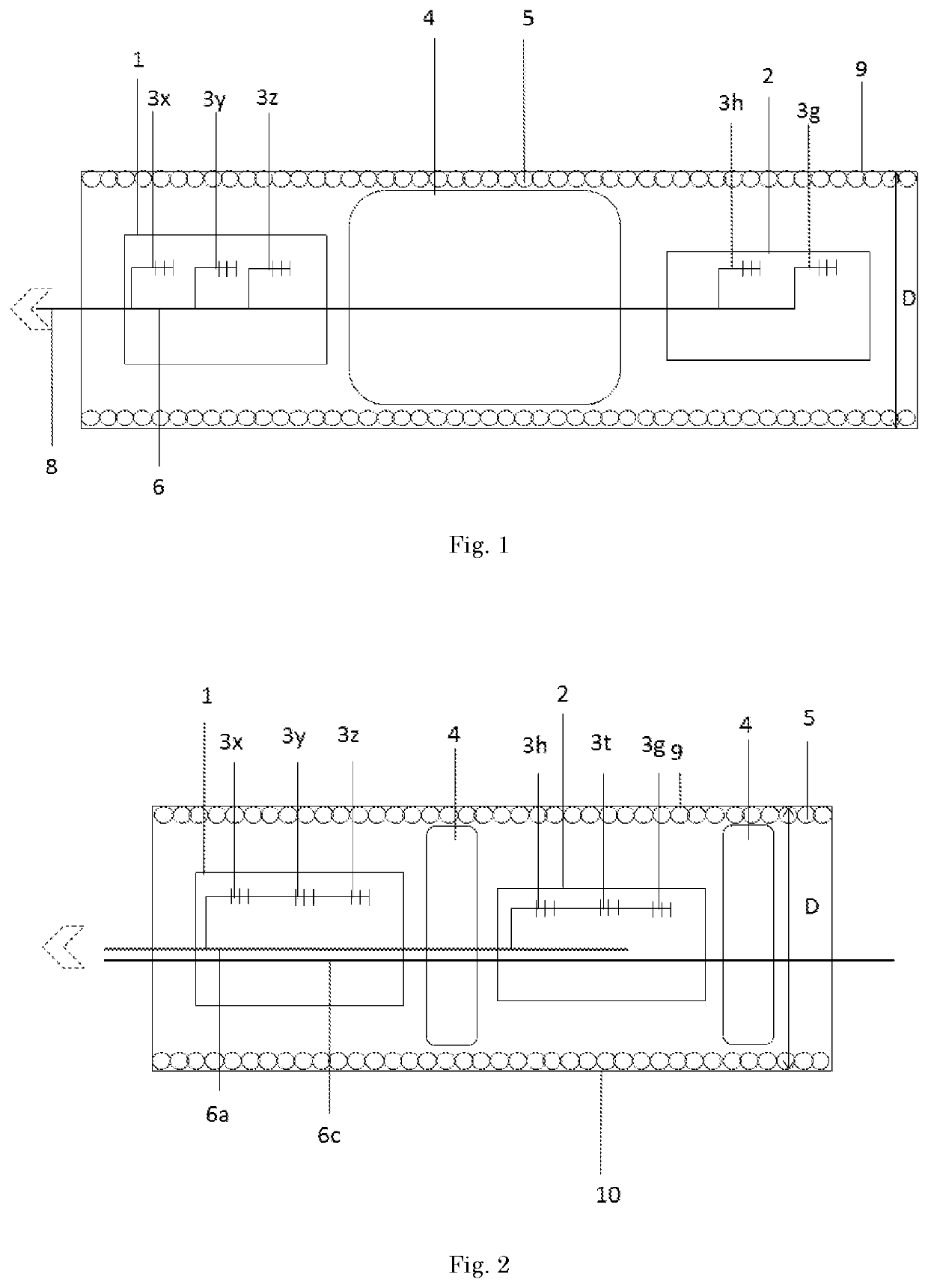
[0040]In one embodiment, the invention relates to an ocean bottom sensing system (OBS) which can be used for ocean bottom sensing. In this embodiment the system comprises a cable such as seen in FIG. 1, wherein at least a first and a second detector (1, 2) are present, further comprising intrinsic fiber optic sensors (3x, 3y, 3z, 3t, 3h, 3g). The sensors can be, for example, Fiber Bragg Grating (FBG) accelerometers (3x, 3y, 3z), FBG hydrophones (3h), FBG geophones (3g), FBG pressure meters, and / or other intrinsic fiber optic sensors such as for temperature (3t). The sensors are connected to an optical fiber (6) for the interrogation thereof through the exiting optical fiber bundle (8) which comprises the optical fiber (6). Alternatively each sensor can be connected to an individual optical fiber (6) and more preferably sensors belonging to each specific detector can be ...


PUM


Abstract

A system for ocean bottom sensing for performing geological survey. Herein the system comprising a cable further comprising a cable jacket (9), at least one optical fiber (6), and a plurality of detectors enclosed by the cable jacket (9). The latter including at least a first and a second detector (1, 2), the at least first and second detector (1, 2) comprising at least one intrinsic fiber optic sensor (3x, 3y, 3z, 3h, 3g, 3t). The detectors are communicatively connected to the at least one optical fiber (6) for allowing interrogation of the intrinsic fiber optic sensors (3x, 3y, 3z, 3h, 3g, 3t) and the cable jacket (9) has substantially a same cross-sectional diameter (D) and same outer shape at the at least first and second detector (1,2) and in between said first and second detector (1,2).

Description

CROSS-REFERENCE TO RELATED APPLICATIONS[0001]This application is a national stage application of International Application No. PCT / NL2016 / 050508, which was filed on Jul. 8, 2016, which claims priority to Netherlands Application Number 2015151 filed on Jul. 10, 2015, of which is incorporated by reference in its entirety.FIELD OF THE INVENTION[0002]The present invention is directed at ocean bottom and maritime sensing systems for geological survey.BACKGROUND[0003]Seismic geological surveys for underwater exploration, especially those in large water depths, is conducted by placing recorders on the seafloor as it provides the detector units to pick up on geological signals which would have been lost by transmission through the sea and / or which through shear waves would be rendered indistinguishable from background events. Additionally, the seafloor provides a stable environment, isolated from sounds, surface waves, temperature fluctuations and background noises which can interfere with ...

Claims


Application Information

Patent Timeline
Patent Type & Authority Patents(United States)
IPC IPC(8): G01V1/20G01V1/22G01V1/38G01H9/00
CPCG01V1/201G01V1/226G01V1/3852G01H9/004
Inventor KARABACAK, DEVREZ MEHMETFARNAN, MARTIN
Owner FUGRO TECH BV
Why Eureka
Try Eureka