Rotary cutter unit for an agricultural mower

a rotary cutter and mower technology, applied in the field of rotary cutter units for agricultural mowers, can solve the problems of large transient load, damage or destruction of one or more gears, and expensive repair, and achieve the effect of preventing disassembly of the rotary cutter unit, and simple and efficient retention mechanism

Active Publication Date: 2020-04-21
KVERNELAND GROUP KERTEMINDE AS
View PDF22 Cites 0 Cited by
  • Summary
  • Abstract
  • Description
  • Claims
  • Application Information

AI Technical Summary

Benefits of technology

[0023]In another embodiment, the inwardly extending retention element comprises a circlip that is located in an inwards-facing slot in the drive output element and engages the radial flange to prevent axial separation of the drive output element from the housing. This provides a very simple and efficient retention mechanism.
[0024]In another embodiment, the retention mechanism includes an outwardly extending retention element on the housing that engages the drive output element to prevent axial separation of the drive output element from the

Problems solved by technology

If one of the rotating cutter discs hits an obstacle such as a rock, this can produce a very large transient load in the drive train, which can damage or destroy one or more of the gears.
This can lead to an expensive repair and an extended idle time while the repair is carried out, possible resulting in loss of the crop.
One problem with the disc cutter unit described in U.S. Pat. No. 4,999,981 is that when the shaft shears the rotating knife holder separates from the housing of the disc cutter and falls to the ground.
Owing to the high kinetic energy of the rotating cutter disc it can then travel a distance of several metres, potentially causing damage to the mower, the

Method used


Image

  • Rotary cutter unit for an agricultural mower
  • Rotary cutter unit for an agricultural mower
  • Rotary cutter unit for an agricultural mower

Examples


first embodiment

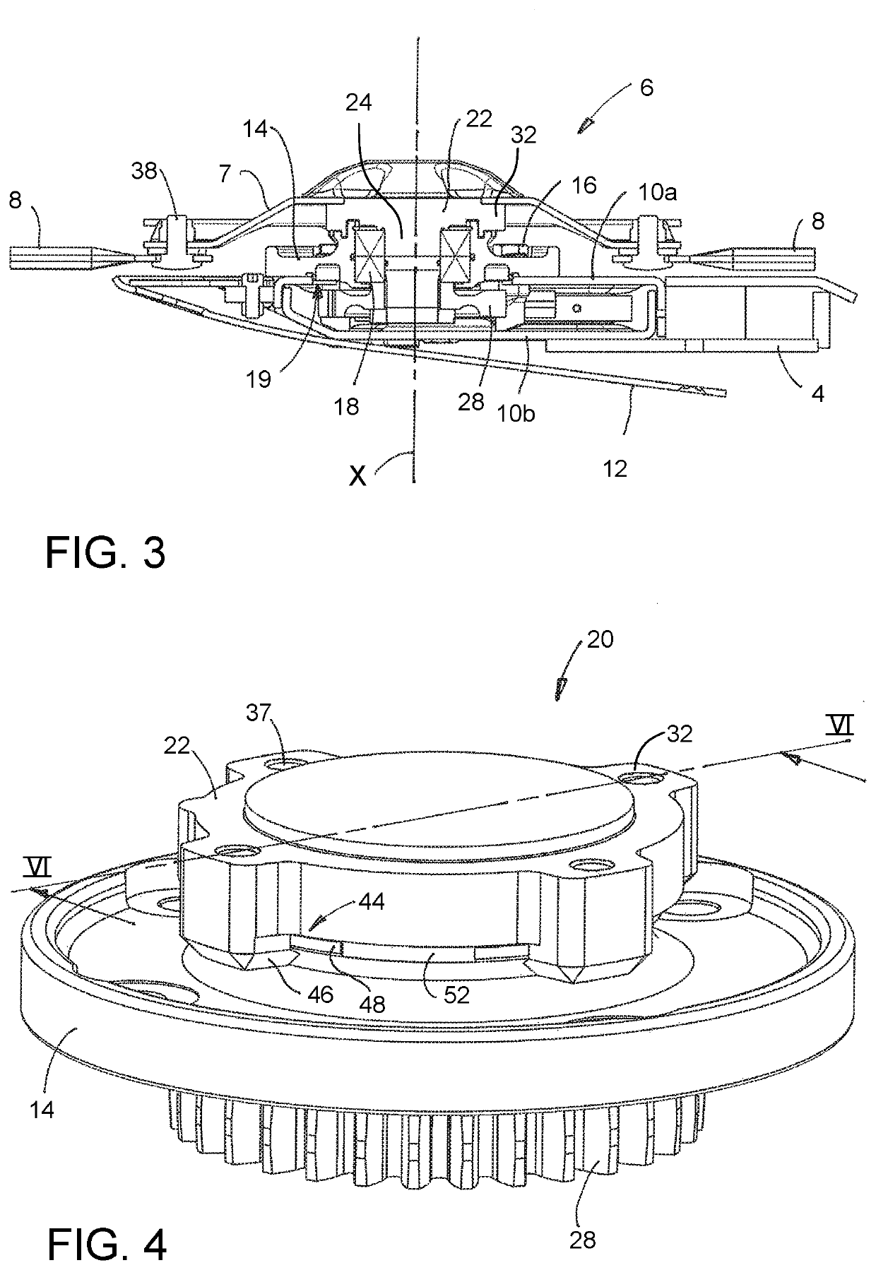
[0059]The structure of a first rotary cutter unit 6 according to the disclosure is illustrated in FIG. 3. Other rotary cutter units forming alternative embodiments of the disclosure are described below and are illustrated in the accompanying drawings: these alternative designs are all variants of the first rotary cutter unit and, except where indicated otherwise, include similar features.

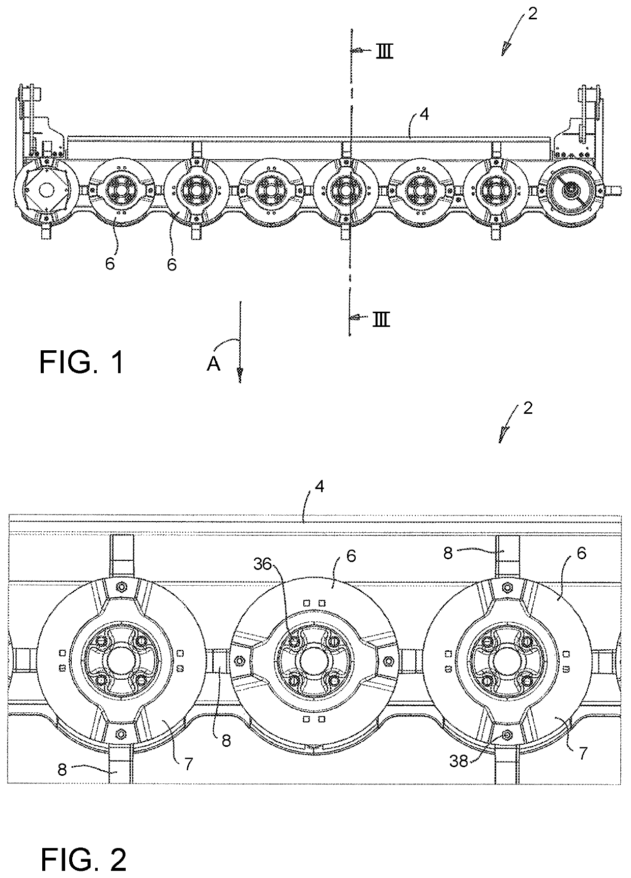
[0060]The rotary cutter units 6 are carried by the cutter bar 4. As illustrated in FIG. 3, the cutter bar 4 consists of an enclosed housing comprising a top plate 10a and a bottom plate 10b. The cutter bar 4 houses a drive mechanism for driving the rotary cutter units 6, which may consist either of a train of gears, for example as described in U.S. Pat. No. 5,715,662, or a drive shaft and a set of transfer gears, for example as described in U.S. Pat. No. 6,675,563. A skid 12 is attached to and extends rearwards beneath the cutter bar 4.

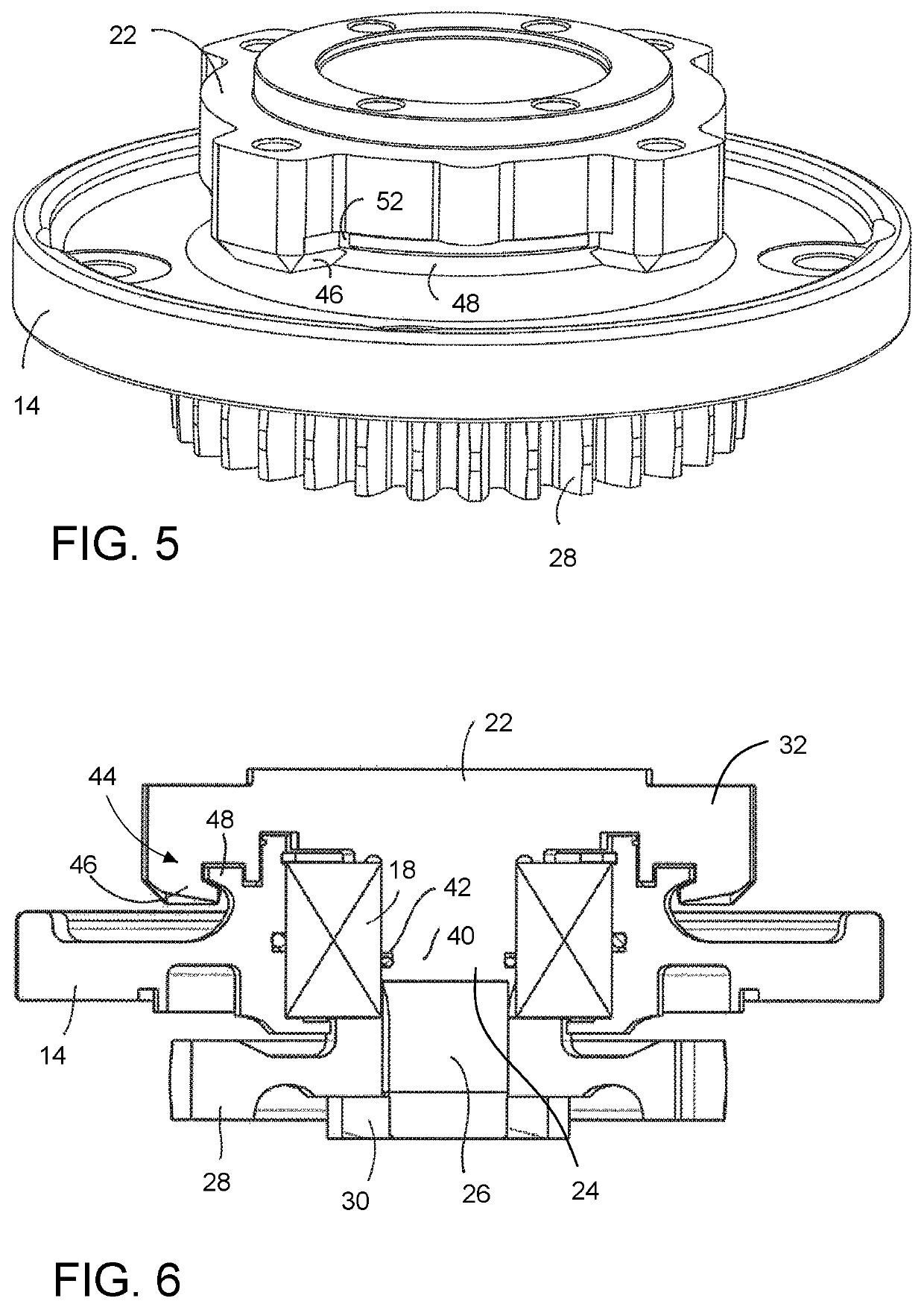
[0061]Each rotary cutter unit 6 includes a housing 14 that is at...

second embodiment

[0073]FIGS. 12-16 illustrate the disclosure, in which the rotary cutter unit 6 is similar in many respects to the first rotary cutter unit, as described above. The foregoing description of the first rotary cutter unit therefore applies equally to the second rotary cutter unit, except as indicated below.

[0074]In this embodiment the retention mechanism 44 includes a pair of lock brackets 60 (or detachable retaining elements) that are attached to the hub flange 32. Each lock bracket 60 has a base plate 61 with a semi-circular inner edge, and three clamping members 62 that extend upwards from the base plate 61, each clamping member 62 having an inwards-extending tongue 63 at its upper end. The tongues 63 engage respective recesses 64 around the peripheral edge of the hub flange 32. When the cutter disc 7 is attached to the hub 22 with bolts 36 as shown in FIG. 16, the cutter disc 7 clamps the lock brackets 60 to the hub flange 32, securing them in position.

[0075]The semi-circular base p...

sixth embodiment

[0086]the disclosure is illustrated in FIGS. 21 to 26. In this embodiment the rotary cutter unit is very similar to that shown in FIG. 20 and the foregoing description therefore applies, except as indicated below. In this embodiment the housing 14 does not include a retaining flange 48, but instead is provided with an outwards facing slot 96, which is provided in the sleeve portion 14a of the housing 14. A corresponding inwards facing slot 98 is provided in a depending portion 100 of the hub flange 32. A retaining ring 102, for example a circlip or a Seeger ring, is located in the slot 96 in the housing 14. The retaining ring 102 is made of an elastic material, for example spring steel or carbon fibre, and it has an outer diameter that is greater than the diameter of the sleeve portion 14a and an inner diameter that is smaller than the diameter of the sleeve portion 14a. The retaining ring 102 is therefore retained within the slot 96, but extends outwards beyond the surface of the s...


PUM


Abstract

A rotary cutter unit (6) for an agricultural mower (2) comprises a housing (14) that carries a rotary bearing (18) having an axis of rotation (X), and a rotor assembly (20) that is supported by the bearing for rotation relative to the housing about the axis of rotation. The rotor assembly includes a shaft (24) that extends through the bearing, a drive input element (28) at an input end of the shaft for transmitting rotary drive to the shaft and a drive output element (32) at an output end (22) of the shaft to receive rotary drive from the shaft. A frangible element (40) comprising a weakened portion of the shaft (24) is provided between the drive input element and the drive output element, which is configured to break when subjected to an excessive load so as to interrupt the transmission of rotary drive between the drive input element and the drive output element. A retention mechanism (44) is provided, which prevents separation of the drive output element from the housing when the frangible element breaks but permits rotation of the drive output element relative to the housing. The retention mechanism includes a retention element (46, 48) that extends substantially radially between the drive output element (32) and the housing (14) to restrict axial movement between the drive output element and the housing.

Description

CROSS REFERENCE[0001]This application is a U.S. National Phase of PCT International Application No. PCT / EP2016 / 064100, filed Jun. 17, 2016 and published as WO 2017 / 012805 on Jan. 26, 2017, which claims priority to U.K. Application No. 15177479.1, filed Jul. 20, 2015. The entire disclosure of each of the above-identified applications is hereby incorporated by reference.BACKGROUNDField[0002]The present disclosure relates to a rotary cutter unit for an agricultural mower, a cutter bar for an agricultural mower, and an agricultural mower that includes a cutter bar. In particular, but not exclusively, the disclosure relates to a rotary disc cutter unit.Certain Related Art[0003]A known type of agricultural mower has a cutter bar that carries a plurality of rotary cutter units. Each rotary cutter unit includes a cutter disc comprising a disc-shaped knife holder that carries a number of knives, which project radially from the edge of the disc. The cutter bar includes a drive mechanism for d...

Claims


Application Information

Patent Timeline
IPC IPC(8): A01D75/18A01D34/66
CPCA01D34/664A01D75/182
Inventor HAVERS, THOMAS
Owner KVERNELAND GROUP KERTEMINDE AS
Why Eureka
Try Eureka