
Angular contact and purely axial bearings with anti-friction separators

Active Publication Date: 2020-04-21
ROMAN NEGRON ALBERTO JOSE
View PDF23 Cites 0 Cited by
  • Summary
  • Abstract
  • Description
  • Claims
  • Application Information

AI Technical Summary

Benefits of technology

This patent describes a new type of anti-friction separator for angular contact bearings. These separators are designed to reduce friction and wear caused by conventional cages, which improves the performance of the bearings and reduces the chances of failure. The anti-friction separators also allow for increased operating speeds, greater load capacities, and economical and easy manufacturing and assembly. They are made of a simple cone shape, which allows for the installation of a larger number of rolling elements in the bearings. Overall, this technology is an improvement for the performance and durability of angular contact bearings.

Problems solved by technology

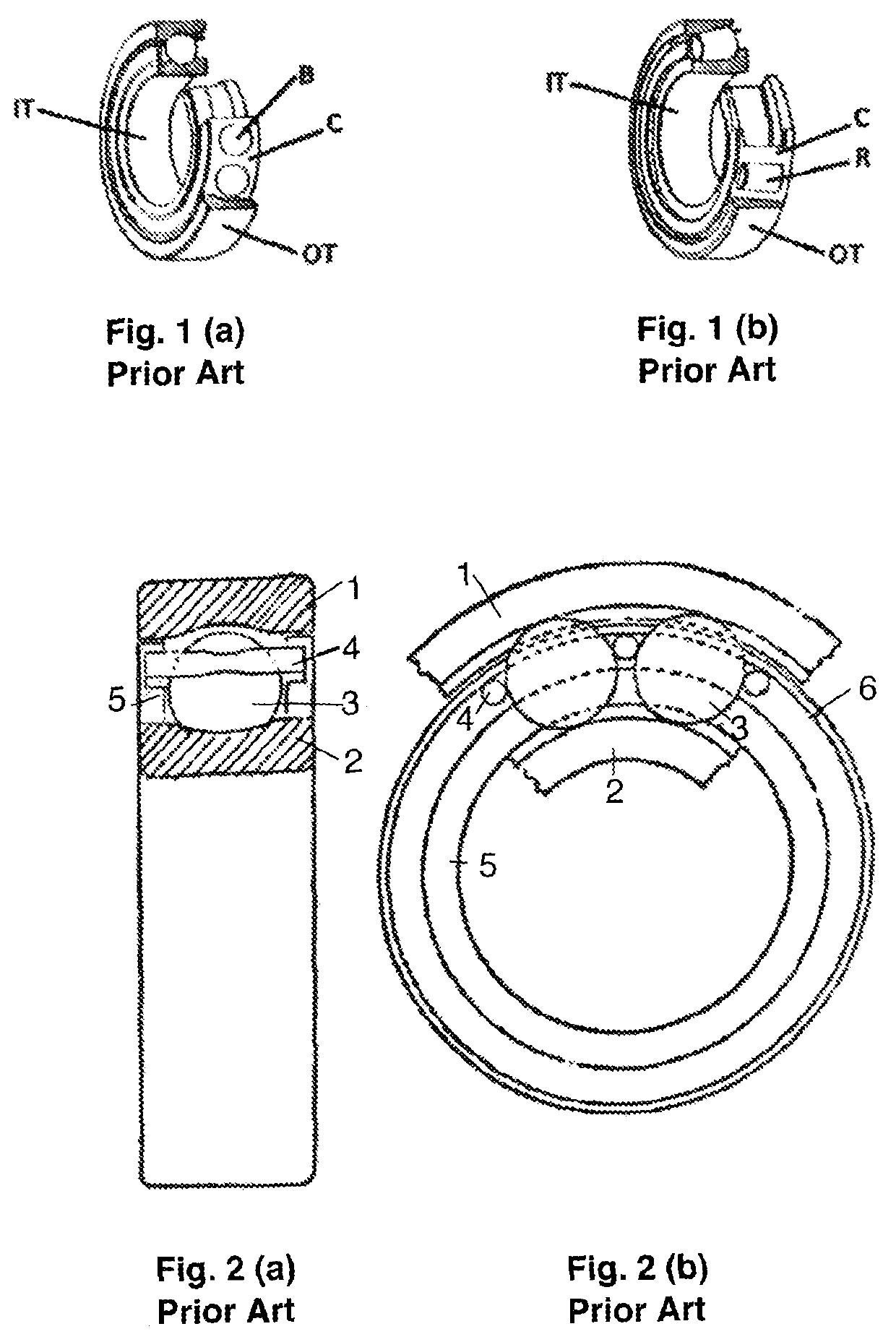
The conventional angular contact bearings include an inner track IT, an outer track OT, balls or rollers B or R, and a cage C. In both of these types of conventional bearings, the contact among the rolling elements B or R and cages C occurs with a high degree of sliding, resulting in friction and wear.
As a result, the cage breaks more frequently than the other components of the bearing.
In some cases, the breaking of the cages is due to fatigue or by high pressure exerted on them by the rolling elements due to centrifugal forces whose magnitudes are directly proportional to the angular velocity of the bearing.
Sometimes, to obtain a better support, the cages additionally contact a track with a high level of sliding which provides an additional source of friction and wear.
The friction and wear usually determine the lower limit of the length of service of the bearings and, at the same time, shortens the fatigue functioning time.
Its synthesis is much more complex than those for radial bearings.
This means that the cylindrical separators for purely radial bearings cannot be used for angular contact bearings and vice versa because the kind of motion that they perform are very different.

Method used


Image

  • Angular contact and purely axial bearings with anti-friction separators
  • Angular contact and purely axial bearings with anti-friction separators
  • Angular contact and purely axial bearings with anti-friction separators

Examples


Embodiment Construction

Introduction

[0030]For convenience of description, the terms “inner”, “outer”, “top”“bottom”, “front”, “rear”, “right”, “left”, “side” and words of similar import will have reference to the various members and components of the bearings of the present disclosure as arranged and illustrated in the figures of the drawings and described hereinafter in detail.

[0031]It should also be understood that the terms “about,”“approximately,”“generally,”“substantially” and like terms, used herein when referring to a dimension or characteristic of a component of the present disclosure, indicate that the described dimension / characteristic is not a strict boundary or parameter and does not exclude minor variations therefrom that are functionally the same or similar, as would be understood by one having ordinary skill in the art.

[0032]The present disclosure relates to angular contact bearings with anti-friction separators such that all bearing parts move with pure rolling contact, i.e., without slidin...


PUM


Abstract

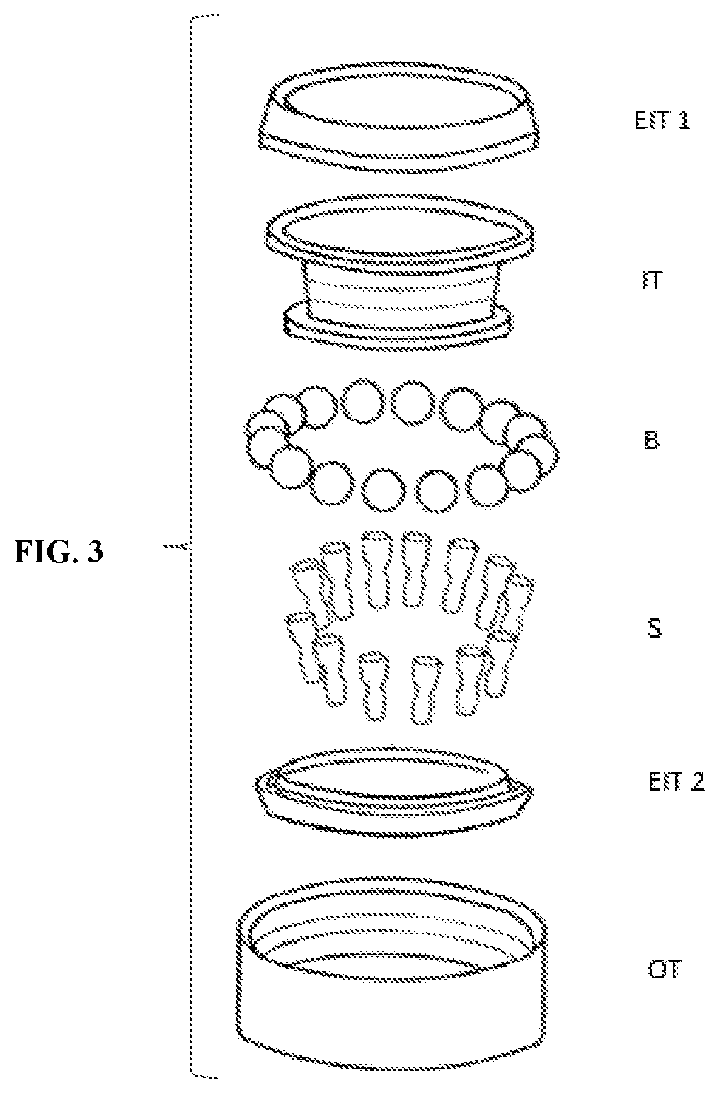
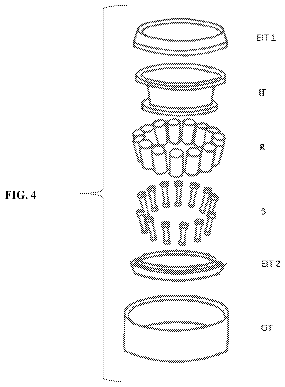
An anti-friction bearing includes a pair of rotatable tracks, a pair of extension members removably securely mounted to one of the pair of tracks, spaced load-carrying rolling members rotatably engageable between the two tracks, and individual spacers disposed to roll on the surfaces of the pair of extensions members. Each of the individual spacers is engageable with and cooperatively separates an adjacent pair of the rolling elements. All of the components of the bearing are disposed in corresponding pure rolling contact, i.e., without sliding, relative one another.

Description

BACKGROUND OF THE DISCLOSUREField of the Disclosure[0001]The present disclosure relates generally to anti-friction bearings and, more specifically, to angular contact and purely axial bearings with anti-friction spacers or separators such that all hearing components move with pure rolling contact, i.e., without sliding contact among the bearing integral parts.Background Information[0002]Conventional angular contact and purely axial bearings are generally formed of two rings or tracks, a predetermined number of rolling elements (e.g., balls or rollers) placed between these tracks, and a single retainer or cage which maintains the rolling elements around the periphery of the tracks equidistantly separated, thus avoiding the high degree of friction that would be generated if those elements would touch each other. The difference between these two types of bearings is that while angular contact bearings can bear radial and axial loads at the same time, the latter in one direction only, p...

Claims


Application Information

Patent Timeline
IPC IPC(8): F16C19/10F16C33/66F16C33/372F16C33/37F16C33/58F16C33/60
CPCF16C33/66F16C33/372F16C19/10F16C33/3706F16C33/605F16C33/585F16C33/3713F16C19/20F16C19/30F16C19/40F16C2300/02
Inventor ROMÁN NEGRÓN, ALBERTO JOSÉ
Owner ROMAN NEGRON ALBERTO JOSE
Learn More