Molded product processing system

a processing system and product technology, applied in the direction of shaping presses, conveyor parts, manufacturing tools, etc., can solve the problems of molded products that have less hardness, molded products that may hit the inner wall or the bottom wall of the chute, and may collide with each other to be damaged,

Active Publication Date: 2020-04-28
KIKUSUI SEISAKUSHO LTD
View PDF10 Cites 2 Cited by
  • Summary
  • Abstract
  • Description
  • Claims
  • Application Information

AI Technical Summary

Benefits of technology

[0010]If each of the modules is accommodated in a containment case inhibiting an external leakage of an atmosphere in the containment case, and applies the post process to the molded products in the containment case, then the system achieves a containment environment with neither halfway discharge of the molded products from the system nor the external leakage of the atmosphere including the powdery material. The system is particularly useful for production of molded products containing a highly pharmacologically active substance. The system also inhibits contamination of the molded products.
[0011]The conveying mechanism included in the module substantially horizontally preferably shifts the plurality of molded products while being kept aligned. This inhibits as much as possible a vertical positional displacement of the molded products to reduce a risk of damage to the molded products dropped due to gravity force. Furthermore, this does not essentially require any lift configured to lift upward the molded products.
[0013]If the compression-molding machine includes a plurality of die bores, and a plurality of pairs of upper punches and lower punches, then the processing mechanism included in the module corresponds to an exterior inspection mechanism that includes a camera configured to image each of the molded products, and is configured to inspect the molded product in terms of an exterior condition, a quality inspection mechanism configured to inspect the molded product in terms of volume, weight, or a component, or a foreign matter detection mechanism configured to inspect the molded product as to whether or not the molded product contains any foreign matter, and a controller includes a storage device configured to store information on a result of an inspection of the molded product by the processing mechanism, in association with identification information on the die bore and the pair of upper and lower punches and used for molding the molded product, the molded product detected to have defectiveness through the inspection can be specified and tracked. This also enables quick specification of the die bore and the pair of punches used for molding such a defective product in the compression-molding machine.

Problems solved by technology

Such a technique obviously causes gradual decrease in height of the molded products and requires disposition of a lift configured to halfway lift upward the molded products.
Furthermore, when the molded products drop onto the chute, the molded products may hit an inner wall or a bottom wall of the chute or may collide with each other to be damaged (e.g., broken, chipped, or abraded).
In particular, molded products having less hardness such as orally disintegrating tablets (OD tablets that disintegrate by saliva or a small amount of water in an oral cavity) or chewable tablets (that are crunched in an oral cavity) are seriously damaged by dropping.
Furthermore, the molded products become not aligned in the order of molding by the compression-molding machine while being transported via the chute.
Upon tableting failure such as sticking of the powdery material kept adhering to a specific one of the die bores or the punches of the compression-molding machine to cause a chipped molded product or mold trouble such as chipping at a tip of one of the punches, a normal molded product and a defective molded product are mixed to be indistinguishable from each other.
A large number of molded products are thus entirely required to be discarded in this case.

Method used


Image

  • Molded product processing system
  • Molded product processing system
  • Molded product processing system

Examples


Embodiment Construction

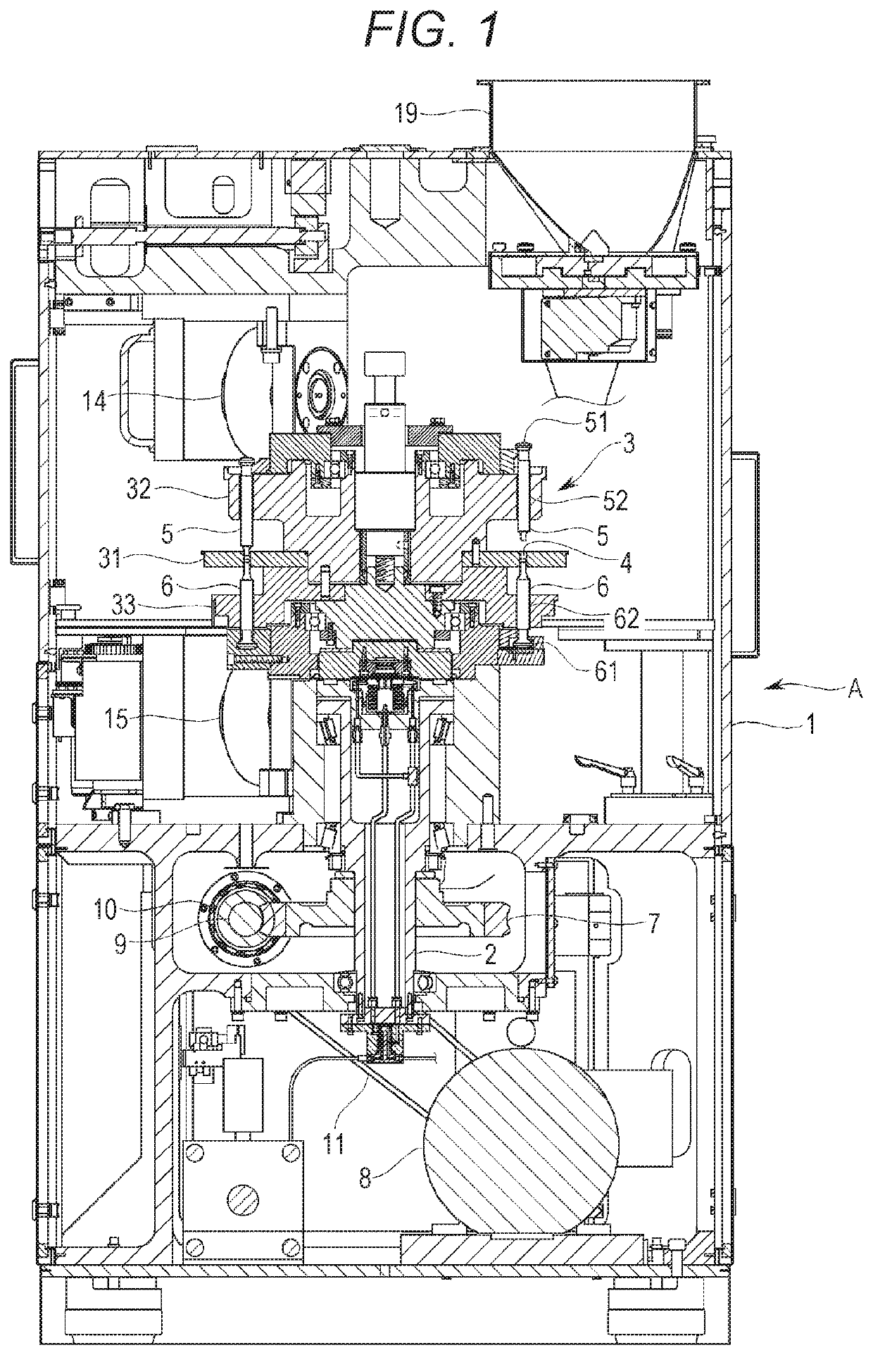
[0034]An exemplary embodiment of the exemplary invention will now be described with reference to the drawings. Initially described is an overview of an entire rotary compression-molding machine (hereinafter, referred to as the “molding machine”) A according to the exemplary embodiment. As shown exemplarily in FIG. 1, the molding machine A includes a frame 1 accommodating an upright shaft 2 functioning as a rotary shaft and a turret 3 attached to a connection portion that is disposed at a top of the upright shaft 2.

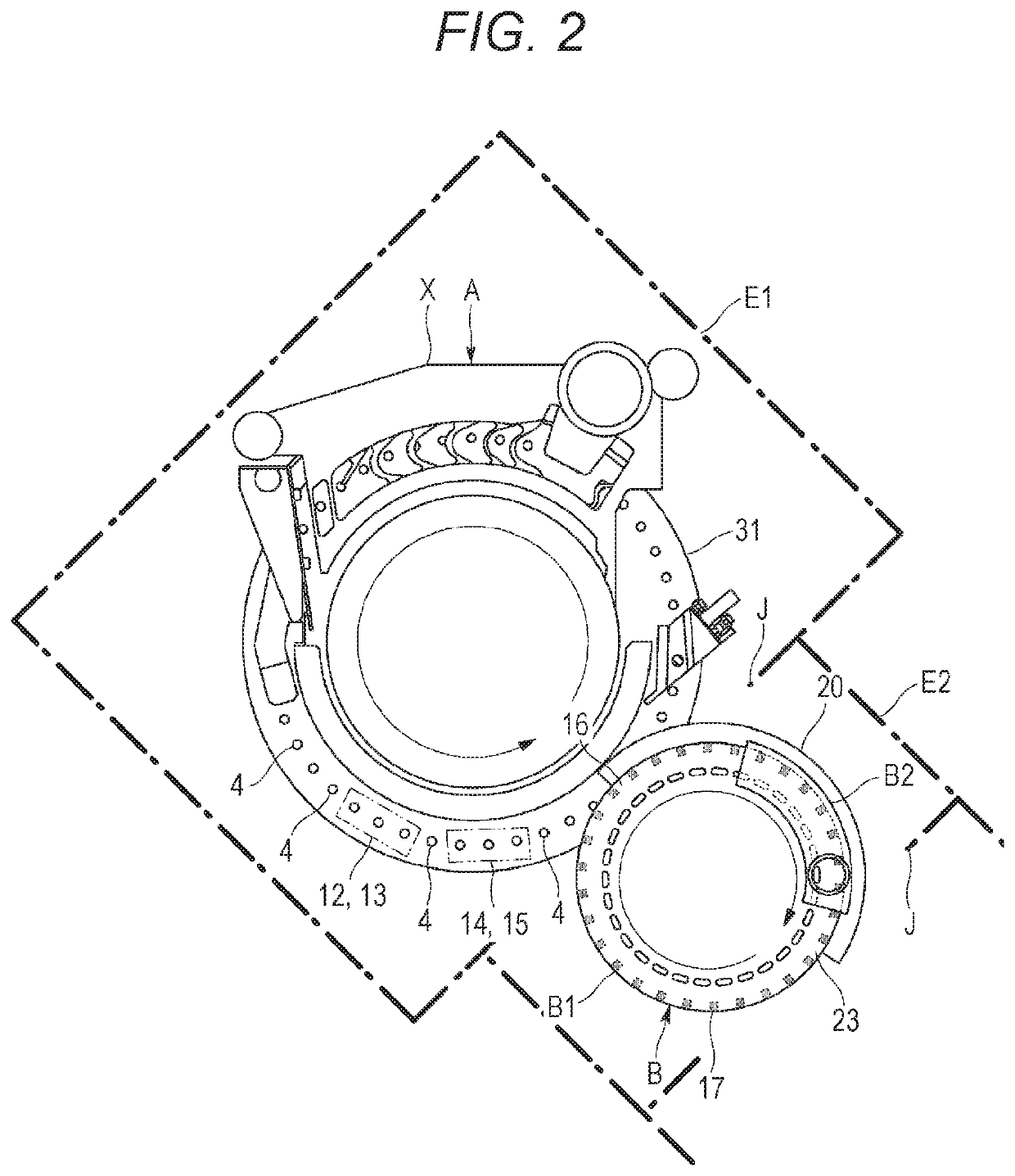
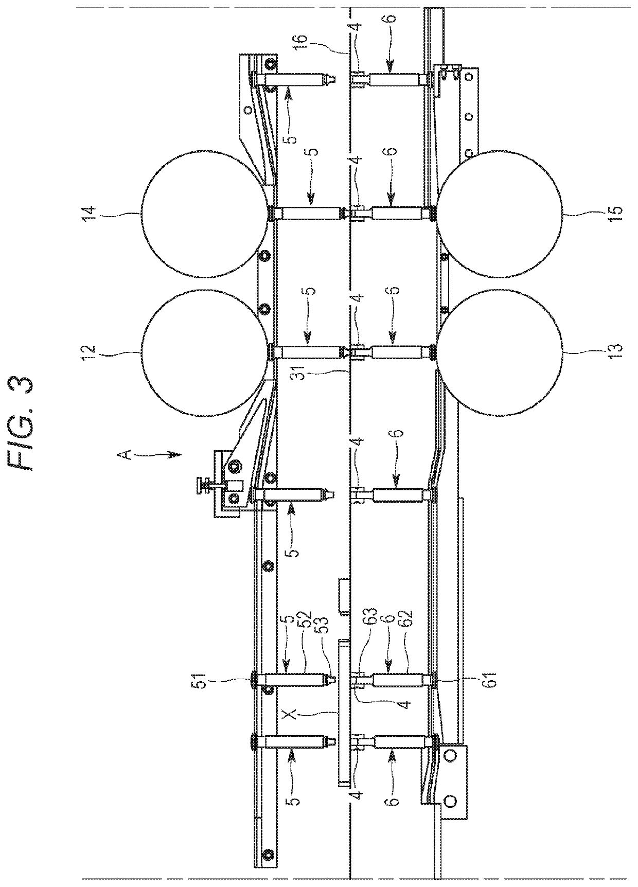
[0035]The turret 3 horizontally rotates about the upright shaft 2, and more specifically, spins. The turret 3 includes a die table (e.g., die disc) 31, an upper punch retaining portion 32, and a lower punch retaining portion 33. As shown exemplarily in FIG. 2, the die table 31 has a substantially circular disc shape in a planar view in a vertical direction, and has a plurality of die bores 4 that is disposed in an outer circumferential portion and is aligned in a rotation ...


PUM

PropertyMeasurementUnit
volumeaaaaaaaaaa
weightaaaaaaaaaa
heightaaaaaaaaaa

Abstract

A molded product processing system is configured to apply a post process to a molded product molded by a compression-molding machine. The system includes modules each including a conveying mechanism configured to convey a plurality of molded products P kept aligned, and a processing mechanism confronting a travel route of the molded products conveyed by the conveying mechanism and configured to apply a predetermined post process to each of the conveyed molded products, in which upstream one of the modules and downstream one of the modules are connected to allow the molded products having gone through certain processing at the upstream one of the modules to be delivered to the downstream one of the modules and be subjected to a different predetermined processing at one of the modules.

Description

BACKGROUND[0001]There has been known a rotary compression-molding machine including a die table of a turret having die bores, an upper punch and a lower punch slidably retained above and below each of the die bores, and configured to horizontally rotate the die table and the punches together to compression mold (or make a tablet) a powdery material filled in the die bores when the paired upper and lower punches pass between an upper roll and a lower roll. The molding machine of this type is applied, for example, to produce pharmaceutical tablets, food products, electronic components, and the like.[0002]Each molded product is subjected to various post processes. Examples of the post processes include inspecting the molded product as to whether or not the molded product has a defective exterior, removing dust adhering to the molded product, inspecting the molded product in terms of volume, weight, or components, inspecting as to whether or not the molded product contains any alien met...

Claims


Application Information

Patent Timeline
Patent Type & Authority Patents(United States)
IPC IPC(8): B29C43/34B30B11/00B30B15/26B30B15/32B30B15/02B30B15/30B30B15/00B30B11/08B65G47/84B30B11/10B29C43/08
CPCB30B15/0023B30B11/08B30B15/32B65G47/846B30B15/26B30B11/10B30B11/005B30B15/302B30B15/022B29C43/08
Inventor SHIMADA, SATOSHIKAKITANI, TOMOHIROSUZUKIKUSUNOKI, HITOSHIWATANO, SATORU
Owner KIKUSUI SEISAKUSHO LTD
Why Eureka
Try Eureka