Optical rotation angle measuring system

a technology of rotation angle and measuring system, which is applied in the field of optical systems, can solve the problems of 67 microradians, inability to avoid the order of a few micrometers, and inability to meet the measurement resolution now required, and achieves the effect of reducing the number of micrometers, and increasing the measurement rang

Active Publication Date: 2020-04-28
ARGES GMBH
View PDF10 Cites 3 Cited by
  • Summary
  • Abstract
  • Description
  • Claims
  • Application Information

AI Technical Summary

Benefits of technology

[0010]It is an object of the invention to provide an optical rotation angle measuring device that is more simple and compact and delivers a more accurate measurement signal over a larger measurement range than prior devices, and which is less sensitive to transverse displacements of the rotation shaft.
[0013]The invention is based on the insight that for the envisaged application the diffraction element needs to project images of its pattern only on small sections of the grating structure and that the information content of the diffraction element is substantially smaller than that of a diffraction element which image has to cover the whole circumferential area of a full-ring grating structure. As a consequence, the diffraction element may have a diameter, for example 3 mm that is substantially smaller than the diameter, for example 30 mm, of the stationary grating structure. Compared with a conventional system having the same measurement resolution, the system according to the invention provides the advantage that the inertial load on the angular decoder can be reduced by a factor that is proportional to the fourth power of the ratio of the diffraction element surface size and the size of the disc carrying the annular grating structure, which factor is 1 / 10000 in our example.
[0019]The source of the illumination beam should be positioned on the axis of rotation of the rotation shaft of the angular decoder, in particular on the axis of rotation of the rotation shaft of a galvanometer. For the axial position of the illuminating source we can have different choices that lead to different embodiments of the invention. In a first embodiment of the invention the illumination beam is a diverging beam; the source of this beam is placed on the same side of the hologram as the detection grating. This embodiment has the advantage of simplicity and low cost, because there are no beam shaping components necessary between the illumination source and the hologram. But this embodiment has two unfavorable properties that are caused mainly by the configuration of the hologram. With a divergent illumination beam, the hologram must have a strong optical power to focus the diffracted radiation in the detection plane. This focusing function can be compared to the focusing of a concave mirror centered on the illuminating source. When the hologram is shifted over a small distance, the diffraction images are also shifted, but over distances twice as large as the shift of the hologram. Because the hologram is fixed on the rotation shaft of the angular decoder, this configuration tolerates only very narrow sideway movements and expansions of the shaft, more in particular in the order of ±10 μm, that are difficult to be realized in the construction of for example a galvanometer scanner. The configuration of the hologram is dependent on a fixed value of the wavelength, i.e. the monochromatic wavelength of the illumination source. When a diode laser is used for illumination, its wavelength can differ for instance over ±5 nm from the given specification. Moreover a change in temperature of the laser will cause a wavelength shift of, for instance 0.2 nm per degree C. Temperature changes in existing galvanometer scanners can be, for instance ±20° C. resulting in possible wavelength changes of ±4 nm around an average temperature. Adding these effects makes wavelength errors of ±10 nm possible. Thus within the context of the present invention, the monochromatic wavelength of the illumination source allows wavelength errors (variations) of ±10 nm possible; in particular wavelength errors (variations) of ±5 nm, for example when a diode laser is used for illumination. For a diode laser with a specification wavelength of =660 nm this means relative wavelength errors Δτ / τ=±1 / 66. The relative errors of the radial and axial position of the diffraction images in this embodiment will be equal to a first order approximation, to the relative wavelength error. With a radius r of the detection grating of 15 mm we will have a Δr sideways shift, hereinafter also referred to as the deflection error Δr of ±0.23 mm, with an axial distance Z of 25 mm from the hologram to the detection plane we will have a focus shift ΔZ of 0.34 mm. These effects can only with difficulty be compensated by the mechanical design of the system, which will increase the manufacturing costs.
[0020]Hence, in a second embodiment the illumination beam is made convergent by a lens between the illumination source and the hologram. This means that the chromatic focusing error ΔZ vanishes; the deflection error Δr remains but can be met by making the radial size of the detection structure large enough, for instance ±0.5 mm. Also in this embodiment the positioning orders due to transverse movements of the rotation shaft can be avoided by making the distance between the rotation center of the hologram and the average position of the diffraction image equal to the distance from the rotation center and the virtual image of the illumination source. The position error due to expansion of the shaft will become a factor of about 7 smaller, so that the tolerance for this expansion movements can be up to 70 μm instead of the 10 μm in the first embodiment of the diffraction element. A disadvantage of this second embodiment is that the optical path from the illumination source to the hologram is roughly 3 times as long as in the first embodiment. This problem can be solved partially by folding the optical path in the space above the detection construction. This will make the axial size of the system larger (for example about 10 mm) and will cost extra components such as prisms and / or mirrors.
[0026]According to another aspect, the present optical system is characterized in that the annular grating section is divided into two radially separated sub-gratings having the same grating period and mutually shifted in the tangential direction over a quarter of the grating period and in that for each of these sub-gratings a separate radiation-sensitive detector is provided. This measure allows detection of the rotation direction of the rotation shaft.
[0030]In another embodiment, a spherical mirror is added to the system of the present invention. By adding a spherical mirror to the system that projects a periodic pattern on a set of detectors, the detector plane (101) can be made flat and perpendicular to the symmetry axis of the system. This makes alignment of the system with the face of the plate (10) carrying the detection structures (16) simpler and also improves the quality of the detector signals.

Problems solved by technology

In practice it appears that such displacements of the order of a few micrometers cannot be avoided.
If r=15 mm a displacement of the cylindrical grating over 1 μm will cause an error in angle measurement of 67 microradians, which is unacceptable in view of the measurement resolution now required.
Moreover, because of its optical outlay and the number of optical elements, the device of DE Patent 10 2011 050 030 cannot be made compact and lightweight.

Method used


Image

  • Optical rotation angle measuring system
  • Optical rotation angle measuring system
  • Optical rotation angle measuring system

Examples


Embodiment Construction

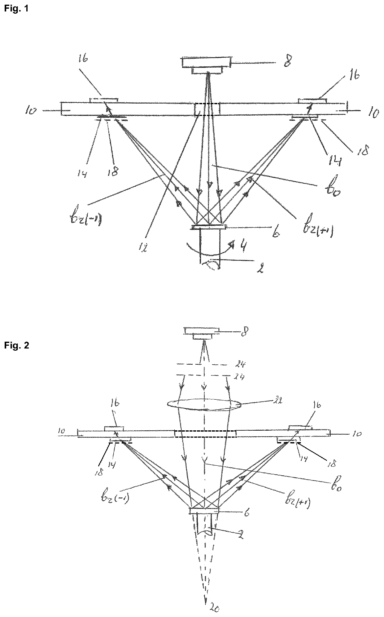
[0042]FIG. 1 shows the principle diagram of the rotation angle measurement system according to the drawings, which is, for example suitable for measuring the angular position of a galvanometer scanner. The rotation shaft of this scanner is denoted by reference number (2). The mirror (not shown in the Figure) of the scanner is mounted on this shaft, which rotation movement is indicated by arrow (4), but should not be understood as limiting the invention to a single direction of rotation. The rotation shaft can rotate in either direction. On one end face of the shaft and perpendicular to the shaft a small and reflective diffraction element (RDE) (6), in particular a hologram (31) is mounted. The diffraction element (6) is illuminated by a spherical radiation beam bo emitted by a monochromatic radiation source, preferably a diode laser (8), which is arranged in line with the rotation axis of shaft (2). The diffraction element splits incident beam bo in sub-beams of different diffractio...


PUM


Abstract

The present invention is directed to an optical system for measuring the rotation angle of rotatable object having a rotation shaft (2), which system comprises a reflective diffraction element (6) mounted on said shaft and a module that includes a radiation source (8) emitting a monochromatic beam (bo) towards this element and a radiation-sensitive detection structure (14, 16), the diffraction element is configured to project diffraction order images (18) of its pattern onto associated sections (50(1)-54(2)) of an annular grating structure forming part of the detection structure and the surface size of the diffraction element is smaller than 20% of the surface size of the annular grating structure.

Description

FIELD OF THE INVENTION[0001]The invention relates to an optical system for measuring the rotation angle of a rotatable object having a rotation shaft, which system includes at the one hand a reflective diffraction element mounted on the shaft and rotating with the shaft and at the other hand a radiation source and detection module, which module comprises:[0002]a radiation source emitting an illumination beam of nearly monochromatic radiation towards the diffraction element; and[0003]a radiation-sensitive detection structure, comprising an annular grating mask, converting illumination beam radiation reflected by the diffraction element into electrical signals suitable for electronic processing to obtain signals representing the said angle.[0004]In a particular embodiment the present invention provides an optical system for measuring the rotation angle of rotatable object having a rotation shaft (2), which system comprises a reflective diffraction element (6) mounted on said shaft and...

Claims


Application Information

Patent Timeline
Patent Type & Authority Patents(United States)
IPC IPC(8): G01D5/347G01D5/38
CPCG01D5/3473G01D5/38G01B11/26
Inventor GUGGENMOS, MARKUSHARTMANN, MARTINKIESBAUER, BERNHARDVELZEL, CHRISTIAAN H. F.PEKELDER, SVENVAN DER KLUIT, RINZE FREDERIK
Owner ARGES GMBH
Why Eureka
Try Eureka