Elongated lead frame and a method of manufacturing an elongated lead frame

a lead frame and elongated technology, applied in the direction of printed circuit aspects, printed circuit non-printed electric components association, light and heating apparatus, etc., can solve the problems of insufficient, limited flexibility of the above discussed flexible led strips and the led 3d curved lead frame of the cited us application, etc., to improve heat management of the light emitter islands, improve heat management, and accelerate the further metal element to the device

Active Publication Date: 2020-05-26
SIGNIFY HLDG BV
View PDF12 Cites 0 Cited by
  • Summary
  • Abstract
  • Description
  • Claims
  • Application Information

AI Technical Summary

Benefits of technology

[0018]The elongated lead frame or the manufactured elongated lead frame is more flexible than the known lead frames. One of the two electrically conductive tracks has a winded portion, which implies, for example, that at the winded portion the electrically conductive track follows a longer path than necessary and this additional length of the electrically conductive track is provided as a winded course, e.g. a meandering course, or follows a meandering path, or as windings. The winded portion allows that a length of the one of the two electrically conductive tracks can be easily enlarged or shortened without having the risk that the one of the two electrically conductive tracks breaks. Thus, the winded portion provides additional flexibility to the one of the two electrically conductive tracks such that the elongated lead frame can be bent. In particular, if the elongated lead frame is laid down on a flat surface, the elongated lead frame can at least once be easily bent by bending a portion of the elongated lead frame away from the flat surface, or by creating a bend in the elongated lead frame while the elongated lead frame is still laying on the flat surface. Also, the elongated lead frame can be easily warped, which means, bended around a longitudinal axis of the elongated lead frame.
[0040]Optionally, at least one of the second patterned layer and the further electrically isolating layer is heat conductive. In other words, the one of the electrically isolating layer and the further electrically isolating layer does not act as a heat isolator and allows the transportation of heat between different layers of the stacks of the light emitter islands. Thereby heat generated in the light emitter is better spread along the light emitter island and the heat can be better provides to an ambient of the elongated lead frame.

Problems solved by technology

This flexibility is rather limited and there is a need for more flexible strip-shaped LED lead frames.
The flexibility of the above discussed flexible LED strips and the LED 3d curved lead frame of the cited US application are limited because 3 conductive layers and 2 isolation layers are stacked or laminated on each other and the flexibility is, for example, not sufficient for the above discussed application in car light sources.

Method used


Image

  • Elongated lead frame and a method of manufacturing an elongated lead frame
  • Elongated lead frame and a method of manufacturing an elongated lead frame
  • Elongated lead frame and a method of manufacturing an elongated lead frame

Examples


Embodiment Construction

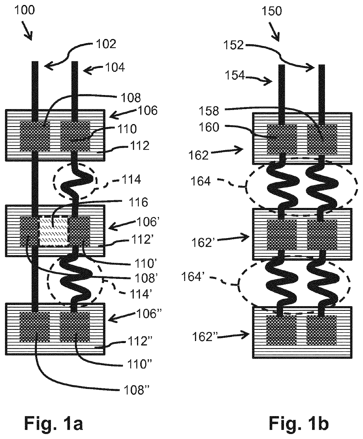
[0059]FIG. 1a schematically shows a top view of an elongated lead frame 100 for a plurality of solid state light emitters 116. The elongated lead frame 100 comprises a plurality of light emitter islands 106, 106′, 106″ that comprise two electrodes 108, 110, 108′, 110′, 108″, 110″. Each light emitter island 106, 106′, 106″ has a rigid structure. In the embodiment of FIG. 1a, the rigid structure is provided by stiffeners 112, 112′, 112″ that are formed by a plate of an electrically isolating material. The plate is made out of a relatively stiff material that is difficult to bend. On the stiffeners 112, 112′, 112″ are provided the two electrodes 108, 110, 108′, 110′, 108″, 110″. Each pair of electrodes 108, 110, 108′, 110′, 108″, 110″ is for receiving a solid state light emitter 116. For example, one solid state light emitter 116 is schematically drawn and indicated with number 116. The elongated lead frame comprises a first patterned layer with two electrically conductive tracks 102, ...


PUM

PropertyMeasurementUnit
temperatureaaaaaaaaaa
electrically conductiveaaaaaaaaaa
conductiveaaaaaaaaaa

Abstract

An elongated lead frame (100) for a plurality of solid state light emitters (116), an elongated lighting assembly and a method of manufacturing an elongated lead frame are provided. The elongated lead frame comprises a first patterned layer (310) of an electrically conductive material and a second patterned layer (320) of an electrically isolating material. The first patterned layer comprising two electrically conductive tracks (102) that comprise first structures (316, 316′) for a first layer of a stack of light emitter islands and two electrically conductive connections between the first structures, at least one of the electrically conductive tracks comprises in between pairs of neighboring first structures a winded portion for forming a flexible electrically conductive connection in between the pairs of neighboring first structures. The second patterned layer comprising second structures for a second layer of the stack of the light emitter islands, the second patterned layer is provided on top of the first patterned layer.

Description

CROSS-REFERENCE TO PRIOR APPLICATIONS[0001]This application is the U.S. National Phase application under 35 U.S.C. § 371 of International Application No. PCT / EP2017 / 055534, filed on Mar. 9, 2017 which claims the benefit of European Patent Application No. 16160301.4, filed on Mar. 15, 2016. These applications are hereby incorporated by reference herein.FIELD OF THE INVENTION[0002]The invention relates to an elongated lead frame for a plurality of solid state light emitters, such as, for example, Light Emitting Diodes (LEDs).[0003]The invention further relates to an elongated lighting assembly.[0004]The invention also relates to a method of manufacturing an elongated lead frame for a plurality of solid state light emitters.BACKGROUND OF THE INVENTION[0005]For car manufacturers it is important to have a signature design for the light sources of the car. Often the light sources comprise a strip shaped light source with Light Emitting Diodes (LEDs) that follows curves in several dimensio...

Claims


Application Information

Patent Timeline
Patent Type & Authority Patents(United States)
IPC IPC(8): H01L33/62H05K1/18H01L21/48H01L23/495H01L25/075H01L33/56H01L33/64H05K3/20F21Y103/10F21Y107/70
CPCH01L33/647H01L23/49575H01L25/0753H01L33/62H01L23/49541H01L21/4821H01L23/4951H01L23/49568H01L33/56H05K1/189H05K3/202H05K2201/2009H05K2201/09263F21Y2107/70F21Y2103/10H05K2201/10106H05K2201/066
Inventor KUMS, GERARDSWEEGERS, NORBERTUS ANTONIUS MARIACROMPOVETS, FLORIS MARIA HERMANSZKLEIJNEN, CHRISTIAN
Owner SIGNIFY HLDG BV
Why Eureka
Try Eureka